RFID reader/writer

a reader/writer and radio frequency identification technology, applied in the near field of read/write/interrogation/identification system, near-field of rfid, instruments, etc., can solve the problems of troublesome task, inability to add an antenna, severely limited use range of rfid reader/writer, etc., to improve installation convenience.

Inactive Publication Date: 2007-08-02
FUJITSU LTD
View PDF15 Cites 14 Cited by
  • Summary
  • Abstract
  • Description
  • Claims
  • Application Information

AI Technical Summary

Benefits of technology

[0016] The object of the present invention is to provide an RFID reader / writer enabling an easy addition of an antenna and improving convenience.
[0018] The present invention eliminates a necessity of a control wire for an antenna changeover in an RFID reader / writer, thereby improving a convenience of installation.

Problems solved by technology

In the case of communicating with an RFID tag by using radio waves, an RFID reader / writer must be capable of communicating with the RFID tag no matter how the RFID tag is positioned, otherwise the usage range of the RFID reader / writer is severely limited.
Especially if there is no terminal for drawing out a control wire for an additional antenna in the reader / writer body 17, a modification thereof or a purchase thereof anew is required, otherwise an addition of an antenna is impossible.
That is, there is a problem of requiring a troublesome task for connecting, and installing, both an antenna cable and a control wire to the reader / writer body.

Method used


Image

  • RFID reader/writer
  • RFID reader/writer
  • RFID reader/writer

Examples


Embodiment Construction

[0036] An embodiment of the present invention is configured to superimpose a command on a high frequency wave signal transmitted from a reader / writer for changing over antennas of an RFID reader / writer according to the command. That is, the embodiment of the present invention eliminates a control wire and improves a convenience of installation of an antenna.

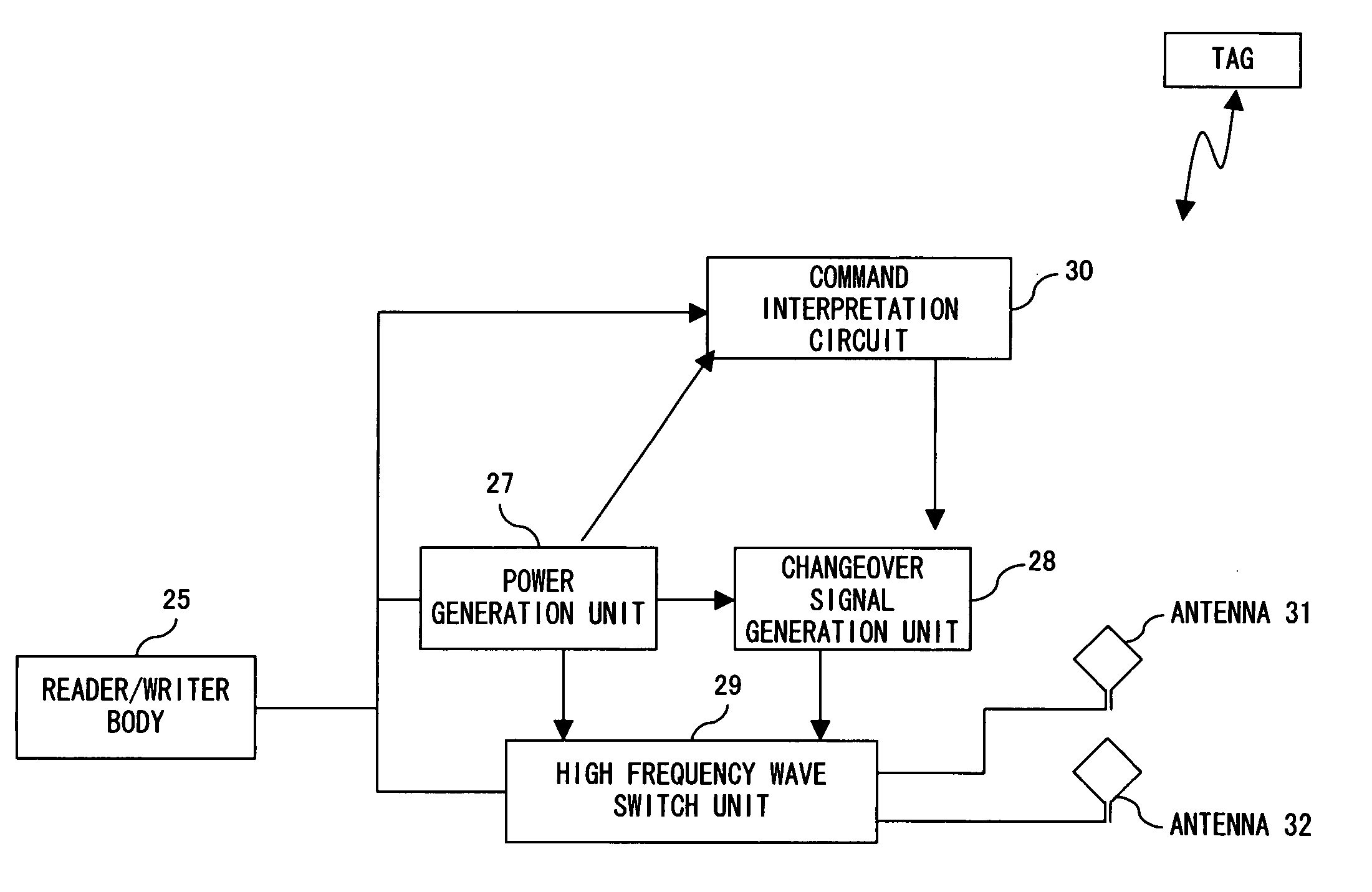
[0037]FIG. 4 is a configuration block diagram of a reader / writer according to an embodiment of the present invention.

[0038] A changeover command is transmitted from a reader / writer body 25 by carried on a high frequency wave toward reader / writer antennas 31 and 32 which are connected to the reader / writer body 25 per se. A command interpretation circuit 30 reads the command and has changeover information generated. That is, the command interpreted by the command interpretation circuit 30 is input to a changeover signal generation unit 28 which then generates a changeover signal based on the interpretation result of the command a...


PUM


Abstract

A reader / writer 25 transmits an instruction for changing over between antennas 31 and 32, carried on a high frequency wave in the same format as a common command. A part of the antenna is equipped with a command interpretation circuit 30 which demodulates a high frequency wave received from the reader / writer body 25 and obtains a command content. If this command is an antenna changeover instruction of the reader / writer itself, the command interpretation circuit 30 instructs a changeover signal generation unit 28 for generating a changeover signal and changes over antennas by controlling a high frequency wave switch unit 29.

Description

BACKGROUND OF THE INVENTION [0001] 1. Field of the Invention [0002] The present invention relates to an RFID (radio frequency identification) reader / writer. [0003] 2. Description of the Related Art [0004] Research and development of a technique for managing goods, et cetera, by attaching thereto an IC chip comprising an antenna and storing identifier information, and externally reading the identifier information from the IC chip by way of radio waves are recently progressing aggressively. An IC chip comprising an antenna is called an RFID tag, while an apparatus emitting radio waves for the purpose of reading identifier information is called an RFID reader / writer. The RFID reader / writer is capable of not only reading identifier information of an IC of an RFID tag but also writing other information to an RFID tag, thus enabling a various applications. [0005] In the case of communicating with an RFID tag by using radio waves, an RFID reader / writer must be capable of communicating with...

Claims


Application Information

Patent Timeline
Patent Type & Authority Applications(United States)
IPC IPC(8): G06K7/08
CPCG06K7/0008H04B5/0062H01Q1/2216G06K7/10346G06K17/00
Inventor MANIWA, TORUKIMURA, SHIGEKAZU
Owner FUJITSU LTD
Why Eureka
Try Eureka