
Snap ring locking clip and method

Inactive Publication Date: 2007-08-02
GM GLOBAL TECH OPERATIONS LLC
View PDF28 Cites 2 Cited by
  • Summary
  • Abstract
  • Description
  • Claims
  • Application Information

AI Technical Summary

Benefits of technology

[0003] The present invention relates to a locking device and method to eliminate rotation or dislodging of a snap ring relative to a snap ring groove. More specifically, the invention relates to a locking clip that may be used as a retention clip, with or without the use of a snap ring.
[0004] In rotating assemblies, the elimination of snap ring movement is needed to control the balance and wear of the assembly. In stationary assemblies, the locking device is needed to control the position of the weaker area of the snap ring, the snap ring gap, to a known and strengthened area of the housing i.e., the snap ring gap is anchored to a stationary part of the housing. The locking clip will also eliminate any possibility of the snap ring coming out of the assembly. In lightly loaded applications the locking device can eliminate the need for the snap ring completely. The item previously retained by the snap ring within a housing assembly may be retained by the locking device only.
[0008] In another aspect of the invention, the locking device further comprises a snap ring fittable into a groove within the housing, wherein the snap ring is circular shaped with a gap in the snap ring; and wherein the locking clip is fittable into the gap in the snap ring, thereby preventing rotation of the snap ring.
[0009] Another aspect of the invention provides a method of limiting movement and thereby balancing a gapped snap ring in a snap ring groove between rotatable parts which includes locating a mass in the snap ring gap in the snap ring groove, wherein the mass is substantially equal to the mass of the material missing from the snap ring to form the gap, whereby to balance the rotation of the parts and snap ring. The method may also include positioning a tab portion of the mass in a clearance between the rotatable parts where such parts are interlocking to assist in the location of the mass and may further comprise locking the mass in the snap ring groove after positioning the tab portion in the clearance.

Problems solved by technology

Rotation or dislodging of the snap ring may lead the snap ring to come out of the assembly.

Method used


Image

  • Snap ring locking clip and method
  • Snap ring locking clip and method
  • Snap ring locking clip and method

Examples


second embodiment

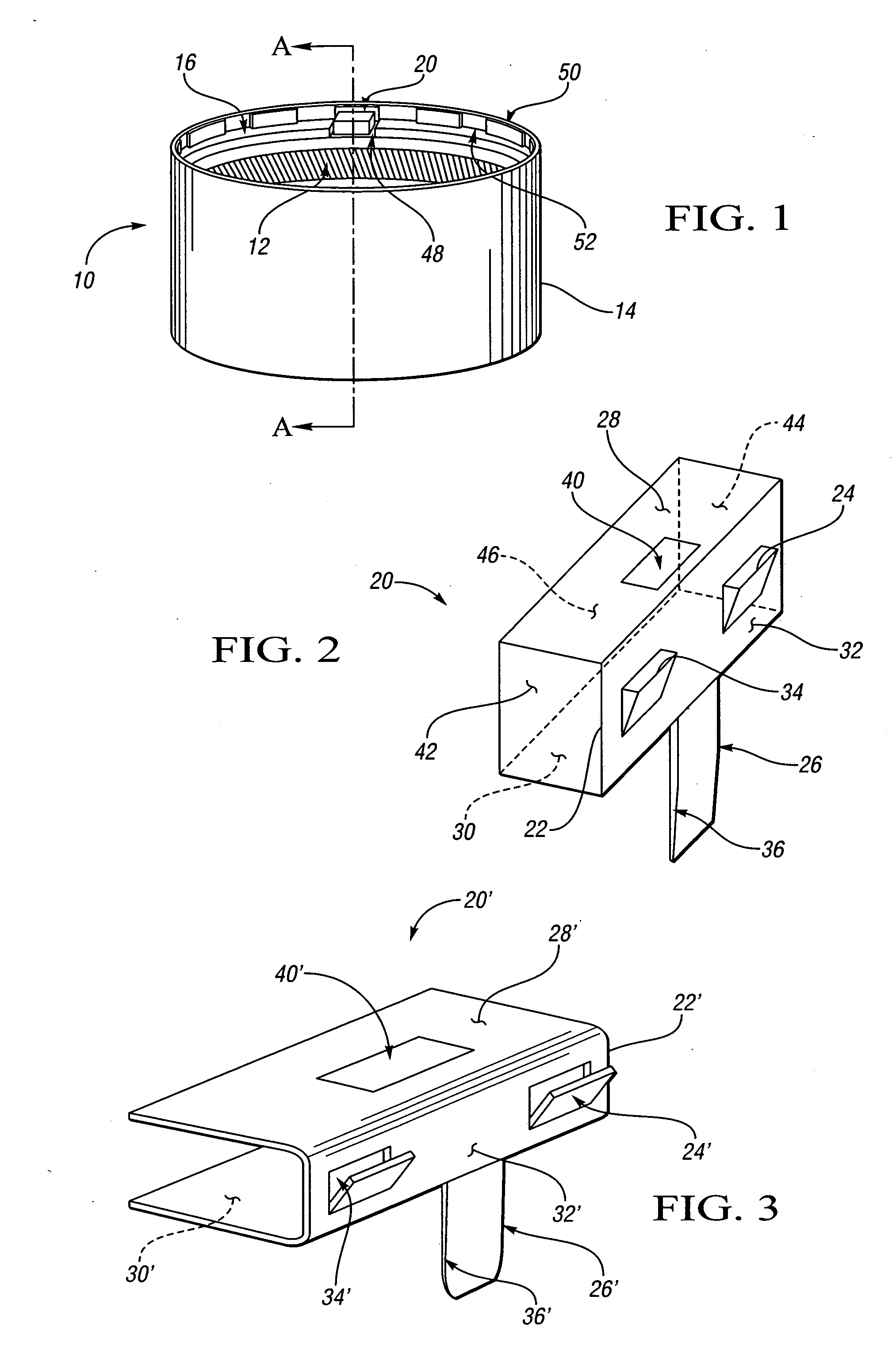
[0028]FIG. 3 is a schematic perspective view of a locking clip 20′, a second embodiment of the invention. The locking clip 20′ includes a clip body 22′, having a first locking tab 24′ connected to the clip body 22′, and a locating tab 26′ connected to the clip body 22′. The clip body 22′ has a top surface 28′, bottom surface 30′ and a first side surface 32′. A first locking tab 24′ and a locating tab 26′ are attached onto or formed integrally on the first side surface 32′. The locating tab 26′ is bendable. A second locking tab 34′ is added onto the first side surface 32′, wherein the first and second locking tabs 24′ and 34′ are on opposite sides of the locating tab 26′. The first and second locking tabs 24′ and 34′ for the locking clip 20′ may be stamped on the first side surface 32′. The locating tab 26′ has a tapered end 36′ to allow for easy insertion during assembly. The bottom surface 30′ of the clip body 22′ is shaped or formed to permit clip assembly clearance 38. A removal ...


PUM


Abstract

A locking device and method to eliminate rotation or dislodging of a snap ring relative to a snap ring groove is provided. A locking clip is provided that may be used as a retention clip, with or without the use of a snap ring. The locking device for a housing assembly to retain a part comprises a locking clip, insertable between the retained part and the housing, wherein the locking clip comprises a clip body; a first locking tab connected to the clip body; and a locating tab connected to the clip body. In rotating assemblies, the elimination of snap ring movement improves the balance and wear of the assembly.

Description

TECHNICAL FIELD [0001] This invention relates to a locking clip that may be used to retain a snap ring and improve balance in rotating assemblies including the snap ring. BACKGROUND OF THE INVENTION [0002] A snap ring is employed to retain a part within a housing assembly. The shape of the snap ring is generally circular, with a gap to allow for insertion of the snap ring into the housing assembly. Rotation or dislodging of the snap ring may lead the snap ring to come out of the assembly. SUMMARY OF THE INVENTION [0003] The present invention relates to a locking device and method to eliminate rotation or dislodging of a snap ring relative to a snap ring groove. More specifically, the invention relates to a locking clip that may be used as a retention clip, with or without the use of a snap ring. [0004] In rotating assemblies, the elimination of snap ring movement is needed to control the balance and wear of the assembly. In stationary assemblies, the locking device is needed to cont...

Claims


Application Information

Patent Timeline
IPC IPC(8): F16L55/00
CPCF16B3/00F16B21/18Y10T24/44017Y10T403/7033F16D1/108
Inventor ROMACK, CARL M.
Owner GM GLOBAL TECH OPERATIONS LLC
Features
  • Generate Ideas
  • Intellectual Property
  • Life Sciences
  • Materials
  • Tech Scout
  • Unparalleled Data Quality
  • Higher Quality Content
  • 60% Fewer Hallucinations
Learn More