Wind turbine generator

a wind turbine generator and vibration control technology, which is applied in the direction of electric generator control, machines/engines, mechanical equipment, etc., can solve the problems of increased cost, increased installation cost, and fluctuation of the rotor, so as to prevent the vibration of the windmill.

Active Publication Date: 2007-08-02
HITACHI LTD
View PDF8 Cites 49 Cited by
  • Summary
  • Abstract
  • Description
  • Claims
  • Application Information

AI Technical Summary

Benefits of technology

[0012]The present invention is developed in view of the above problems regarding the conventional technology. An object of the invention is to present a wind turbine generator which enables controlling of a fluctuation in torque loaded on the rotor, to suppress or prevent vibration of the windmill.
[0018]By this fluctuation, a moment is caused in the tower to suppress the detected vibration, and the vibration is thereby suppressed. By suppressing vibration, a predetermined level of power generation performance can be maintained.
[0022]By this control, resonance with the fluctuation of the rotor as the source of vibration can be prevented. By preventing resonance, a predetermined level of power generation performance can be maintained.
[0024]Preferably, the control device controls the rotor so as to avoid fluctuation of the rotor at a predetermined frequency, when a signal outputted by the sensor exceeds a predetermined threshold value.
[0025]According to such a generator, the same effects as the above invention can be obtained by setting the control device at a predetermined frequency such as the resonance frequency obtained with respect to each windmill.

Problems solved by technology

In this control process, the torque of the rotor may fluctuate and become a vibration source.
However, even in the above-mentioned conventional technology, there are problems such as the followings.
The wind turbine generator as recited in the Patent Document 1 additionally requires a vibration control device, which leads to additional cost.
Further, because the vibration control device is to be installed in the tower, it may not be possible to install the vibration control device in a windmill utilizing inside of the tower as a passage leading into an upper part of the windmill.
On the other hand, it may not be possible to have a passage inside the tower if the vibration control device is installed.

Method used


Image

  • Wind turbine generator
  • Wind turbine generator
  • Wind turbine generator

Examples


first embodiment

[0038]Now, the first embodiment will be explained.

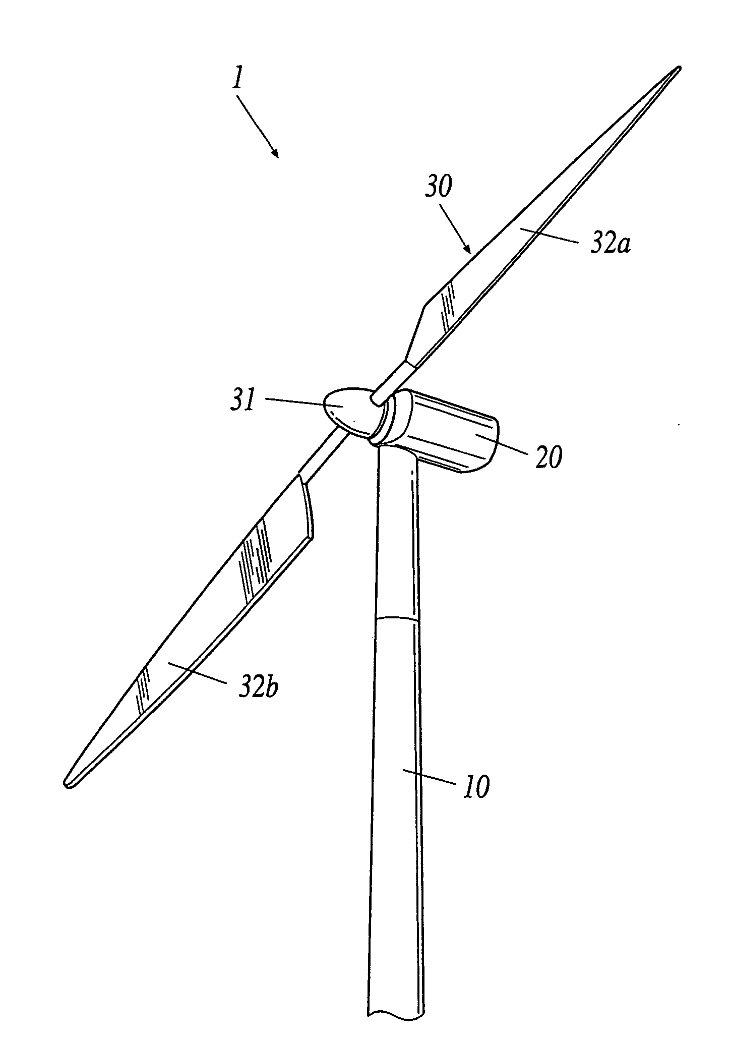
[0039]FIG. 1 is a perspective view showing the external appearance of a wind turbine generator 1 of the invention. The wind turbine generator 1 utilizes a horizontal axis wind turbine. The wind turbine generator 1 comprises a tower 10, a nacelle 20 disposed on the top of the tower 10, a main shaft (not shown) supported by and extending from the nacelle 20 in the approximately horizontal direction of the nacelle 20, blades 32a and 32b attached to the main shaft through a hub 31.

[0040]In the nacelle 20, various machinery such as a generator, a gear box, a control device and the like are installed. The nacelle 20 is rotatably disposed on the top of the tower 10.

[0041]A rotor 30 has the hub 31 attached to an end on the main shaft, and the two blades 32a and 32b attached to the hub 31. The windmill with two blades is shown just as an example; any number of blades will be appropriate. In the hub 31, a pitch drive device is located to drive...

second embodiment

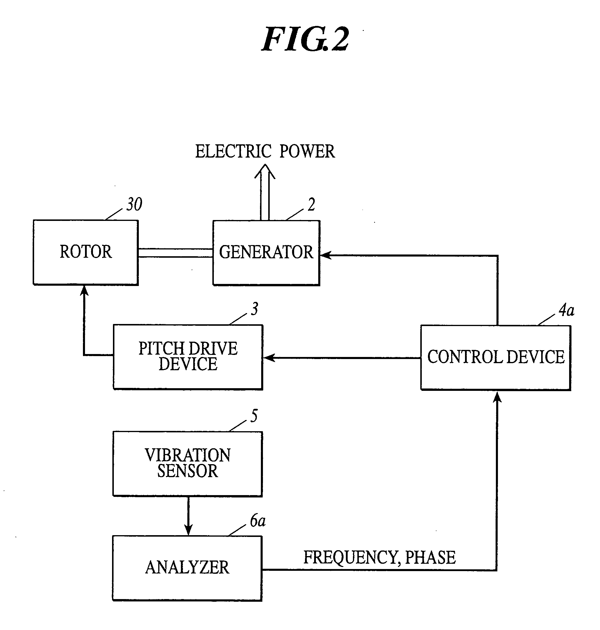
[0055]Next, the second embodiment will be explained. The present embodiment is operable, as the first embodiment described above, with the structure shown in FIGS. 1 and 2. It is sufficient for the analyzer 6a to analyze and output only the frequency.

[0056]In the embodiment, the following vibration control is performed. FIG. 5 is a flow chart of vibration control of the embodiment. When the signal outputted by the vibration sensor 5 exceeds a predetermined threshold (step B1), the analyzer 6a analyses the frequency of the vibration based on the signal outputted by the vibration sensor 5, to output the signal and the analysis result to the control device 4a (step B2). When controlling to cause fluctuation regarding the rotor 30 such as changing the load of the generator 2, changing the pitch angle of the blades, the control device 4a determines the control value of the generator 2 and / or a pitch drive device 3 so as to avoid fluctuation of the rotor 30 at the frequency analyzed by th...

third embodiment

[0059]Next, the third embodiment will be explained. The present embodiment is operable, as the first embodiment described above, with the structure shown in FIG. 1. FIG. 6 is a block diagram of a control system. The rotor 30, the generator 2, the pitch drive device 3, and the vibration sensor 5 are identical with those in the first embodiment, while a control device 4b and an analyzer 6b are different from those in the first embodiment.

[0060]The analyzer 6b in the present embodiment is for analyzing the phase of the vibration component detected by the vibration sensor 5; the analyzer 6b receives the signal outputted by the vibration sensor 5, performs phase analysis based on real-time measurement, and outputs the signal outputted by the vibration sensor 5 together with the analyzed phase to the control device 4b.

[0061]The control device 4b includes a frequency setting section 7. The frequency setting section 7 is disposed in a storage device provided in the control device 4b. The f...


PUM


Abstract

A wind turbine generator includes: a tower; a rotor supported by the tower to rotate around a rotational axis which is not parallel with an axis direction of the tower by wind power; a generator driven by a rotational force of the rotor; a sensor to detect vibration component in a direction perpendicular to the rotational axis of the rotor; and a control device to control the rotor so that fluctuation of the rotor is caused to suppress the vibration component.

Description

CROSS-REFERENCE TO RELATED APPLICATION[0001]This application claims priority to Japanese Patent Application No. 2006-024233 filed on Feb. 1, 2006, which is incorporated herein by reference in its entirety.BACKGROUND OF THE INVENTION[0002]1. Field of the Invention[0003]The present invention relates to a vibration control of a wind turbine generator.[0004]2. Description of Related Art[0005]Presently, in order to stably generate electric power from natural wind, a wind turbine generator utilizing a horizontal axis wind turbine has been proposed and implemented. Such a wind turbine generator includes a rotor, a nacelle, and a tower. The rotor includes a hub and blades. The nacelle is connected with the hub and supports the rotor through a main shaft extending in an approximately horizontal direction. The tower is disposed in an approximately perpendicular direction and supports the nacelle. In the nacelle a generator connected with the main shaft is provided to compose a wind turbine ge...

Claims


Application Information

Patent Timeline
Patent Type & Authority Applications(United States)
IPC IPC(8): F03D9/00H02P9/04
CPCF03D7/0296F03D7/042Y02E10/725F05B2270/334Y02E10/723F05B2260/96Y02E10/72
Inventor NAGAO, TORU
Owner HITACHI LTD
Why Eureka
Try Eureka