Liquid crystal display apparatus which performs display by using electric field in direction substantially parallel with substrate surfaces to control alignment direction of liquid crystal molecules

a liquid crystal display and electric field technology, applied in non-linear optics, instruments, optics, etc., can solve the problems of reduced aperture ratio and dark display image, and achieve the effect of bright image, increased contrast and aperture ratio

Active Publication Date: 2007-08-02
UNIFIED INNOVATIVE TECH
View PDF7 Cites 43 Cited by
  • Summary
  • Abstract
  • Description
  • Claims
  • Application Information

AI Technical Summary

Benefits of technology

[0008] It is an object of the present invention to provide a liquid crystal display apparatus which can eliminate light leak in a peripheral portion of each pixel and increase contrast and an aperture ratio to display a bright image.

Problems solved by technology

Further, when a black mask is provided in order to avoid this light leak, there occurs a problem that an aperture ratio is reduced and a display image is darkened.

Method used


Image

  • Liquid crystal display apparatus which performs display by using electric field in direction substantially parallel with substrate surfaces to control alignment direction of liquid crystal molecules
  • Liquid crystal display apparatus which performs display by using electric field in direction substantially parallel with substrate surfaces to control alignment direction of liquid crystal molecules
  • Liquid crystal display apparatus which performs display by using electric field in direction substantially parallel with substrate surfaces to control alignment direction of liquid crystal molecules

Examples


first embodiment

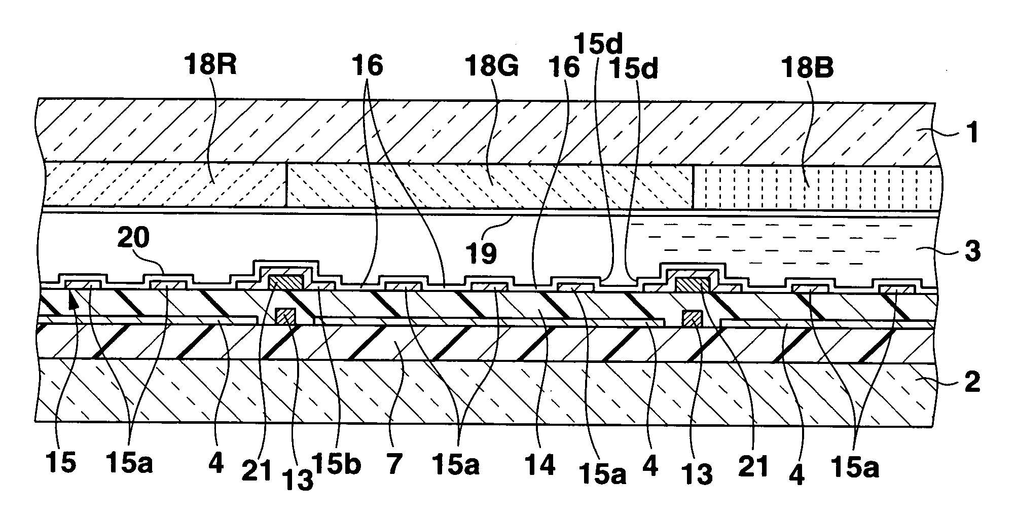
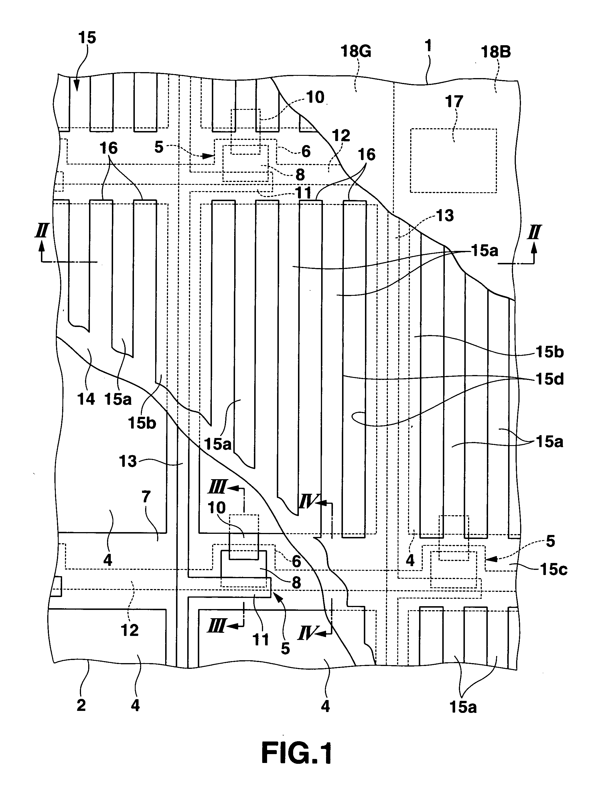
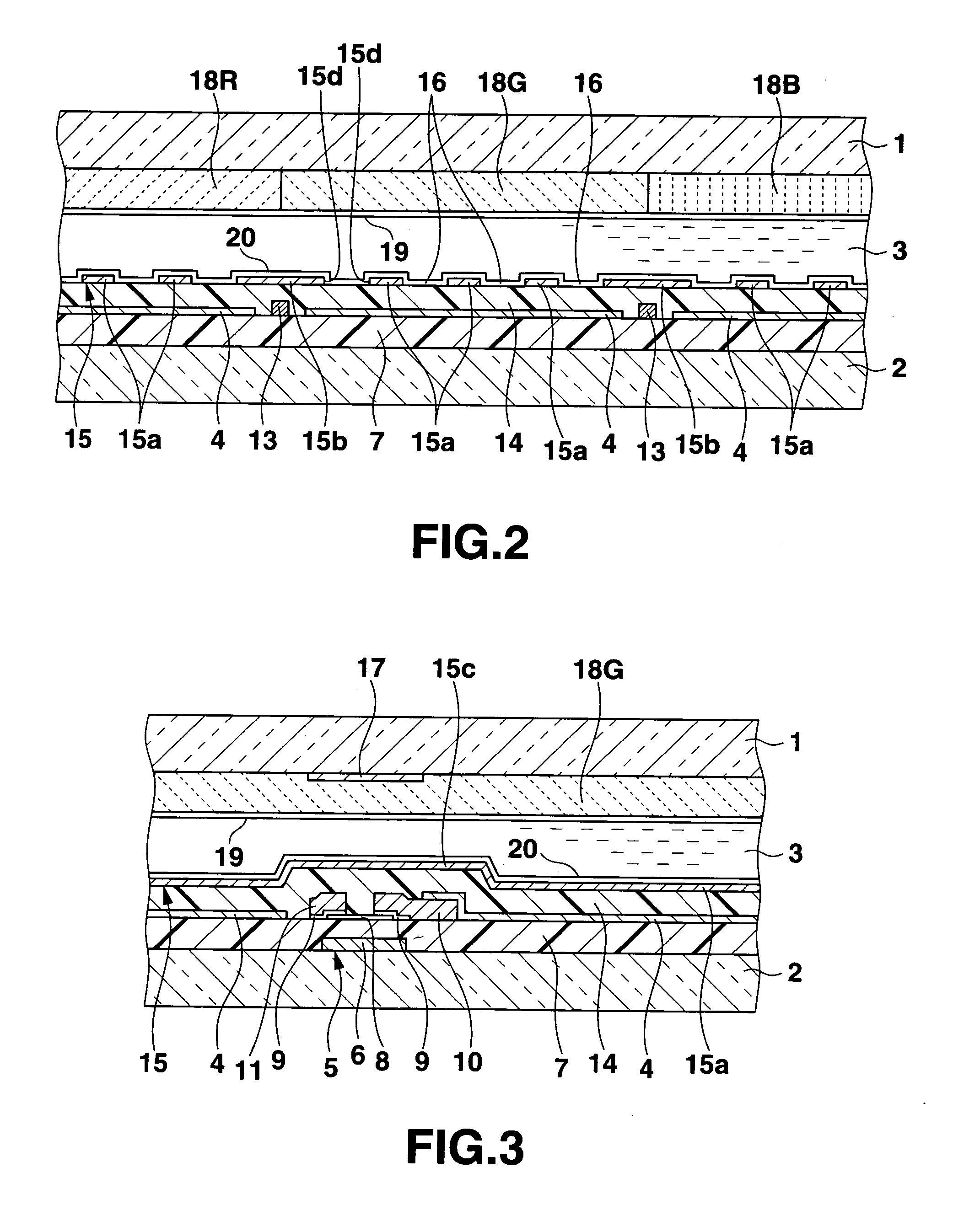
[0066] FIGS. 1 to 4 show a first embodiment of the present invention, in which FIG. 1 is a plan view showing a part of a liquid crystal display apparatus, FIG. 2 is a cross-sectional view taken along a line II-II in FIG. 1, FIG. 3 is a cross-sectional view taken along a line III-III in FIG. 1 and FIG. 4 is a cross-sectional view taken along a line IV-IV in FIG. 1.

[0067] This liquid crystal display apparatus is an active matrix liquid crystal display apparatus, and a liquid crystal layer 3 in which liquid crystal molecules are aligned in substantially parallel with surfaces of a pair of transparent substrates 1 and 2 facing each other with a gap therebetween with long axes being aligned in one direction is disposed between the substrates 1 and 2 as shown in FIGS. 1 to 4. On one of opposed inner surfaces of the pair of substrates 1 and 2, i.e., an inner surface of the one substrate, e.g., the substrate 2 on the opposite side of a display observation side (an upper side in FIGS. 2 and...

second embodiment

[0092]FIGS. 5 and 6 show a second embodiment of the present invention, in which FIG. 5 is a plan view showing a part of a liquid crystal display apparatus and FIG. 6 is a cross-sectional view taken along a line VI-VI in FIG. 5.

[0093] In the liquid crystal display apparatus according to this embodiment, a common electrode line 21 constituted of a metal electroconductive film having a low resistance is provided at a portion of the common electrode 15 corresponding to a region between the pixel electrodes 4 along an entire length of this region, and other structures are the same as those in the first embodiment. Therefore, like reference numerals denote members equal to those in the first embodiment, thereby eliminating their explanation.

[0094] Each common electrode line 21 is formed on the interlayer insulating film 14 in parallel with the scanning or line at a position overlapping the scanning or line to correspond to one of a region between the adjacent pixel electrodes 4 with the...

third embodiment

[0101]FIGS. 7, 8 and 9 show a third embodiment of the present invention, in which FIG. 7 is a plan view showing a part of a liquid crystal display apparatus, FIG. 8 is a cross-sectional view taken along a line VIII-VIII in FIG. 7 and FIG. 9 is a cross-sectional view taken along a line IX-IX in FIG. 7.

[0102] In the liquid crystal display apparatus according to this embodiment, common electrode lines formed of a metal electroconductive film having a low resistance are formed in a reticular or grid pattern to correspond to both regions each positioned between adjacent pixel electrodes 4 with the signal line 13 therebetween and regions each provided between the adjacent pixel electrodes 4 with the scanning line 12 therebetween in addition to partial electrodes 15a. Other structures are the same as those in the second embodiment. Therefore, like reference numerals denote members equal to those in the second embodiment, thereby eliminating their explanation.

[0103] In this liquid crystal...


PUM

PropertyMeasurementUnit
angleaaaaaaaaaa
electricaaaaaaaaaa
electric fieldaaaaaaaaaa

Abstract

A liquid crystal display apparatus includes a liquid crystal layer which is disposed in a gap between first and second substrates with long axes of liquid crystal molecules being aligned in one direction, in substantially parallel to substrate surfaces. A plurality of thin film transistors are arranged in row and column directions on an upper side of the first substrate. Pixel electrodes are provided on the upper side of the first substrate to be electrically connected with the thin film transistors. A common electrode is formed on the upper side of the first substrate between the substrate and the liquid crystal layer to correspond to the pixel electrode through an insulating film, and generates an electric filed which controls an alignment direction of the liquid crystal molecules in a plane substantially parallel with the substrate surfaces between itself and the pixel electrode.

Description

CROSS-REFERENCE TO RELATED APPLICATIONS [0001] This application is based upon and claims the benefit of priority from prior Japanese Patent Application No. 2006-022438, filed Jan. 31, 2006, the entire contents of which are incorporated herein by reference. BACKGROUND OF THE INVENTION [0002] 1. Field of the Invention [0003] The present invention relates to a liquid crystal display apparatus which performs display by using an electric field parallel with substrate surfaces to control a direction of liquid crystal molecules in a plane parallel with the substrate surfaces. [0004] 2. Description of the Related Art [0005] As a liquid crystal display apparatus, there is known one having a configuration in which a liquid crystal layer having liquid crystal molecules aligned in substantially parallel with substrate surfaces with long axes being aligned in one direction is provided between a pair of substrates facing each other with a gap therebetween. Pixel electrodes and a common electrode ...

Claims


Application Information

Patent Timeline
Patent Type & Authority Applications(United States)
IPC IPC(8): G02F1/1343
CPCG02F1/134363G02F1/1343G02F1/1337
Inventor SHIMOMAKI, SHINICHI
Owner UNIFIED INNOVATIVE TECH
Why Eureka
Try Eureka