Method for increasing the information density in signal-transmission lines

Inactive Publication Date: 2007-08-02
ROBERT BOSCH GMBH
View PDF9 Cites 8 Cited by
  • Summary
  • Abstract
  • Description
  • Claims
  • Application Information

AI Technical Summary

Benefits of technology

[0003] The method provided by the present invention allows the information density of information transmitted on a signal line to be increased, where, in particular, a plurality of independent information items may be transmitted via one and the same line. The provided m

Problems solved by technology

However, PWM interfaces have the disadvantage that only information items regarding one physical v

Method used


Image

  • Method for increasing the information density in signal-transmission lines
  • Method for increasing the information density in signal-transmission lines
  • Method for increasing the information density in signal-transmission lines

Examples


Embodiment Construction

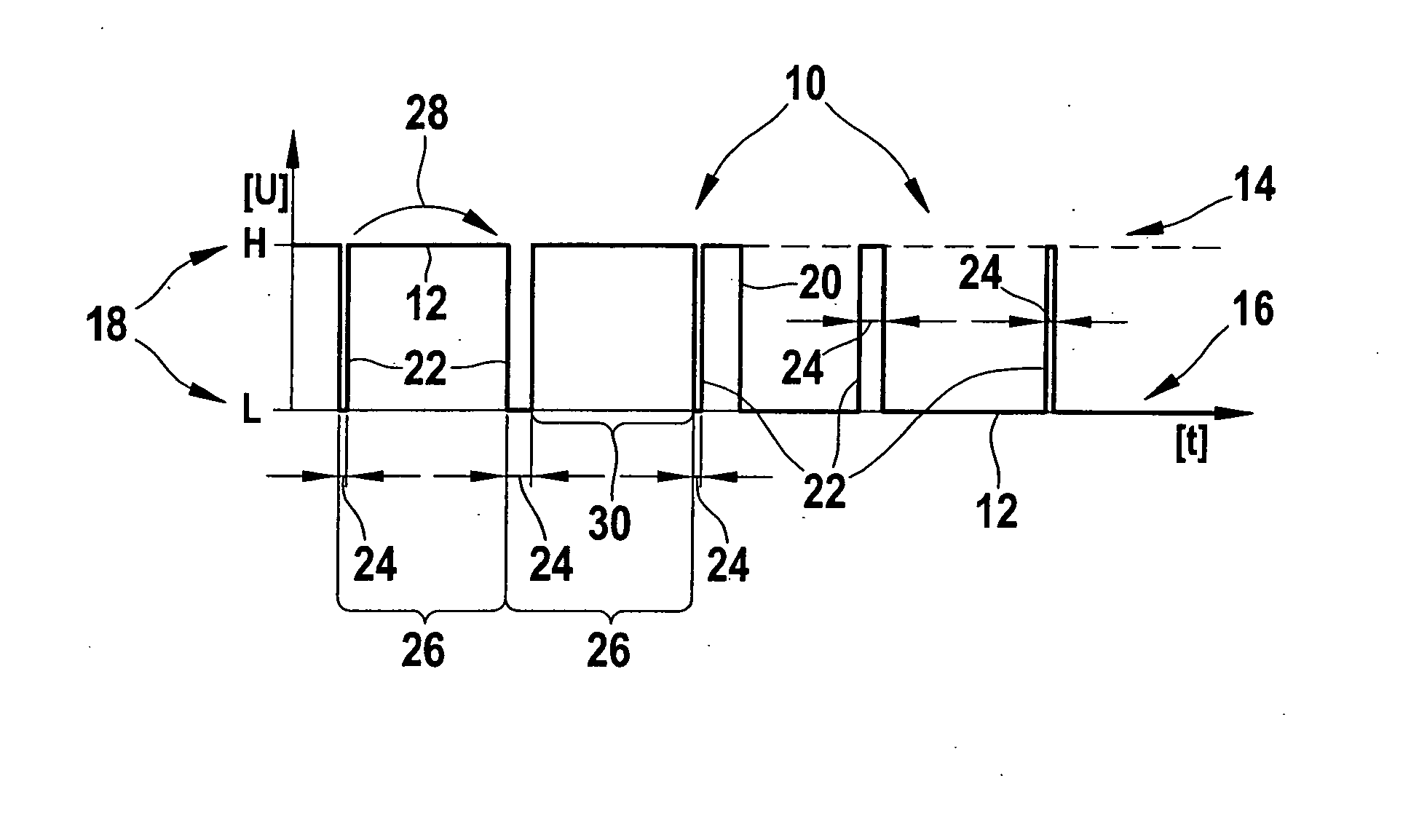
[0016] An exemplary embodiment of the modulated signal provided by the present invention, where a further, encoded pulse signal is superimposed on a digital carrier signal, may be taken from the representation of FIG. 1.

[0017] A modulated signal 10 provided by the present invention includes a digital signal 12 used as a carrier signal. Digital signal 12 may assume a level 18, which corresponds to either a high level 14 (H) or a low level 16 (L). Digital signal 12 of modulated signal 10, shown in FIG. 1, has a level change 20, at which high level 14 of digital signal 12 changes into low level 16. High level 14 corresponds to the level of the supply voltage, whereas low level 16 corresponds to the sensor ground.

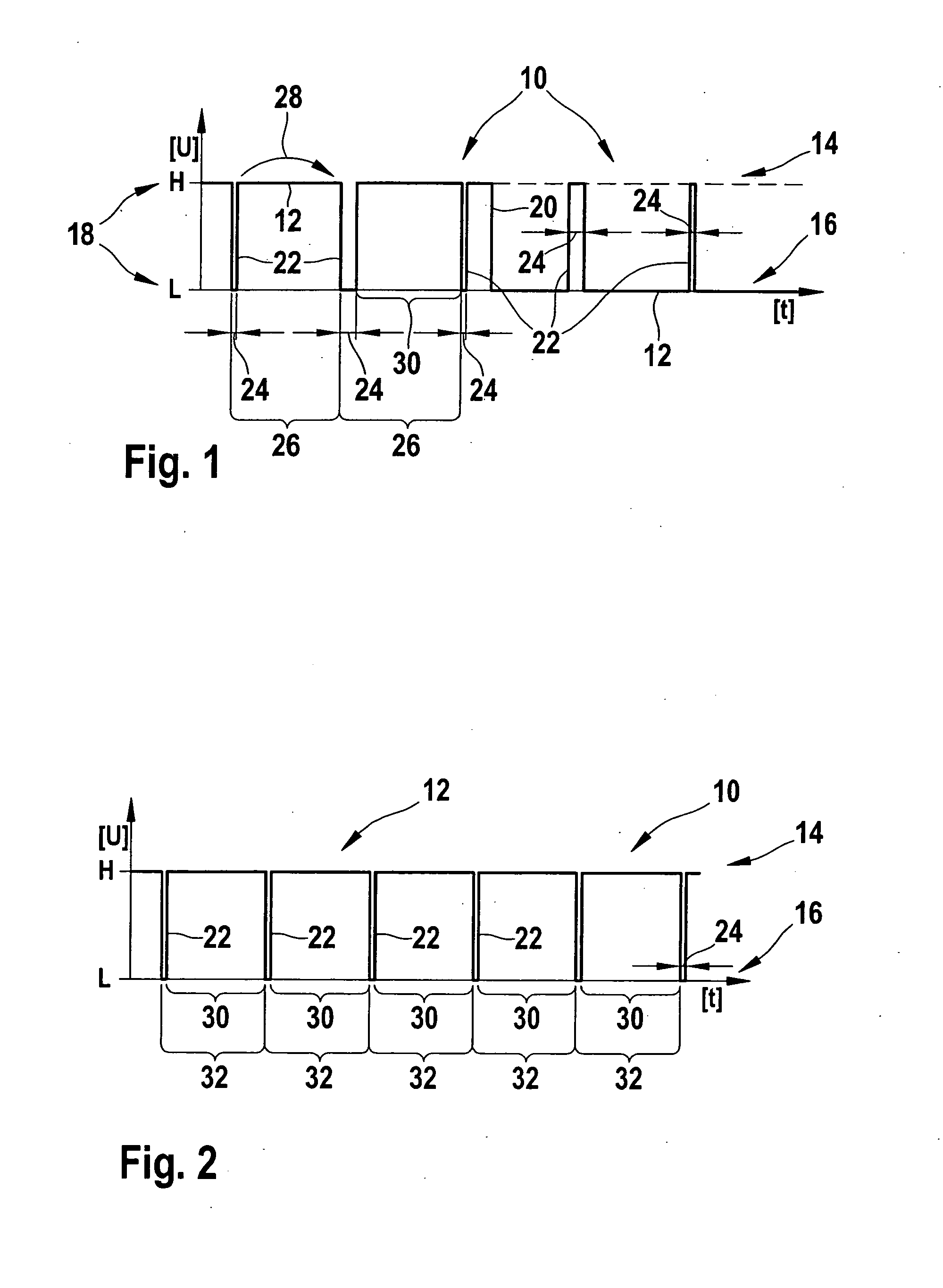
[0018] Digital signal 12 is superimposed with an encoded pulse signal 22. Encoded pulse signal 22 includes individual pulses, which are generated at a predefined pulse frequency 26. The individual pulses are separated from each other by interpulse periods 30, which correspond...


PUM


Abstract

A method for increasing the information density on a signal-transmission line. The signal-transmission line extends from a sensor to a control unit. A modulated signal, which includes a digital signal, is transmitted on the signal-transmission line. The digital signal assumes either a high level or a low level. The modulated signal includes an encoded pulse signal, which is superimposed on the digital signal and has both an encoded pulse duration and a variable pulse frequency.

Description

BACKGROUND INFORMATION [0001] In automatic transmissions, which are increasingly being used in motor vehicles, sensors are used which transmit more than one information item. One example is the engine-speed sensor, which measures both the rotational speed and the direction of rotation. The measured information items may be transmitted to a control unit via digital signals, e.g., via a bit code, or via analog signals, thus, e.g., using the ratio of signal voltage to sensor supply voltage. In order to achieve a high degree of transmission reliability, PWM (pulse-width-modulation) interfaces are increasingly being used. In the case of these, the ratio of the pulse width, also known as the pulse duration, and the signal period, also known as the period, is evaluated. However, PWM interfaces have the disadvantage that only information items regarding one physical variable can be transmitted. It is not possible to transmit independent variables via PWM interfaces. [0002] A sensor for a tr...

Claims


Application Information

Patent Timeline
IPC IPC(8): H02H3/08
CPCH04L25/4902
Inventor WEIBERLE, PETERBISCHOFF, CLAUSGERHAEUSSER, MARTINHAUEFELEIN, STEFFEN
Owner ROBERT BOSCH GMBH
Why Eureka
Try Eureka