
Retromodulation-based data communication

a data communication and retromodulation technology, applied in the direction of electrical equipment, electromagnetic transmission, fibre transmission, etc., can solve the problems of limited field of view, frequent need to change batteries in such controllers, and limited application freedom to make full use of ir ports, so as to achieve the effect of minimal energy consumption

Inactive Publication Date: 2007-08-02
IRALINK
View PDF26 Cites 30 Cited by
  • Summary
  • Abstract
  • Description
  • Claims
  • Application Information

AI Technical Summary

Problems solved by technology

A problem relating to retromodulating units used in prior art is the limited field of view, which requires optical alignment in order to realize the retro communication.
Another limitation of prior art is that it focuses on single line communication: one retromodulator to one transceiver.
Battery capacity thus acts as a limitation on the freedom of applications to make full use of the IR port.
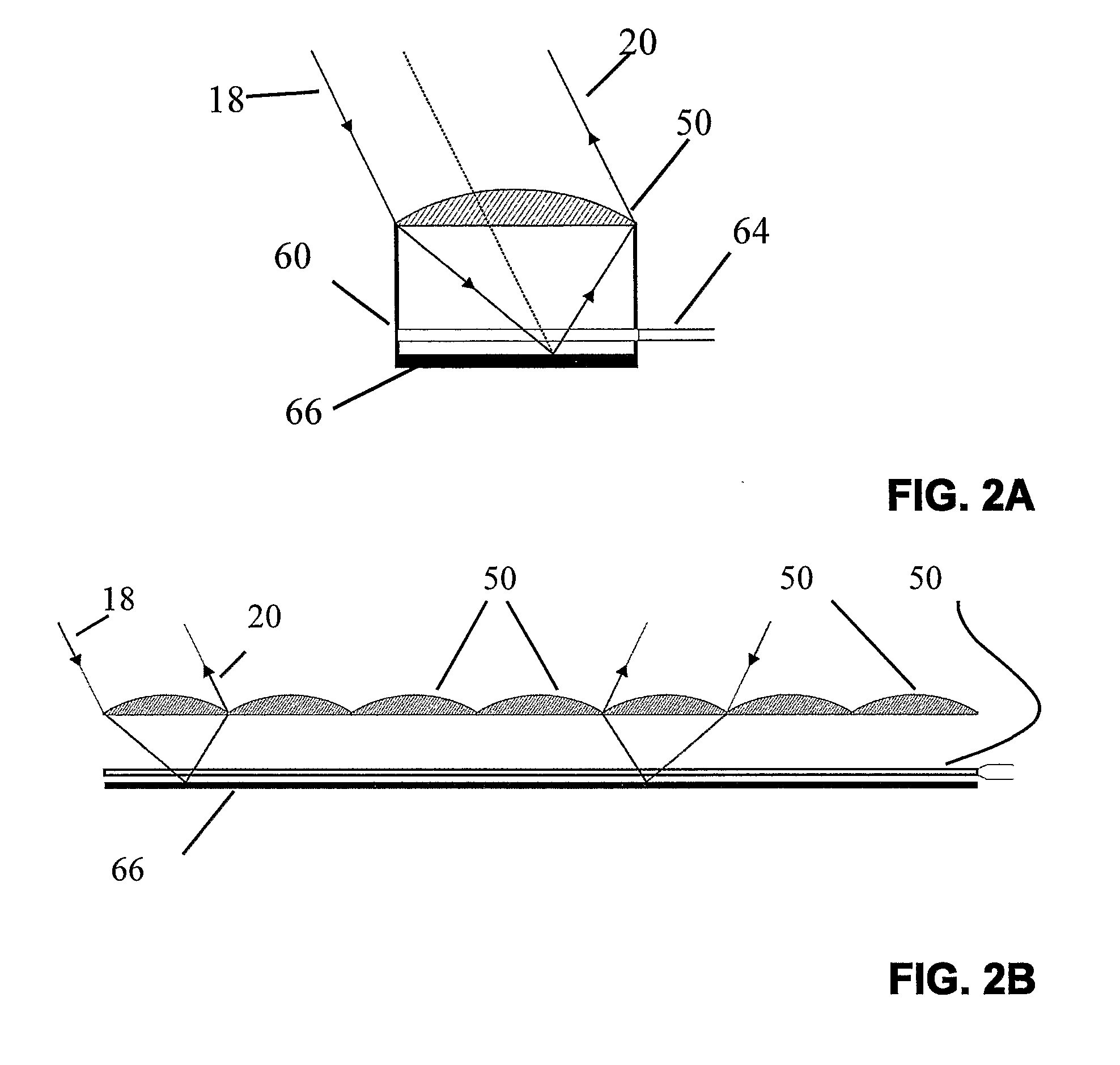
A challenge in constructing a retromodulation-enabled portable device is to provide the retromodulator with a wide enough acceptance field of view that it can retroflect incident radiation from transceivers situated anywhere in a predetermined three-dimensional area around the device, where that area may extend as far as to comprise the complete 360 degrees of surrounding space.
The frequent need to change batteries in such controllers is inconvenient.
There have been cases where the guard was unable to remotely detect a suspicious person, culminating with a fatal attack taking the lives of the guard as well as many innocent citizens.
In some applications, the number of sensors may be very large, to the extent of making battery replacement impractical.
In other cases, change of the battery is so inconvenient that the introduction of the sensor into the market depends on energy saving, namely on very low consumption of energy.
The process of removing the memory and physically providing it to a development facility is time consuming and often requires waiting in line.
However, transmitting the information is energy consuming and cameras batteries normally don't last long enough.
In some cases retromodulated communication is not possible due to a lack of line of sight between transceiver and retromodulator.

Method used


Image

  • Retromodulation-based data communication
  • Retromodulation-based data communication
  • Retromodulation-based data communication

Examples


Embodiment Construction

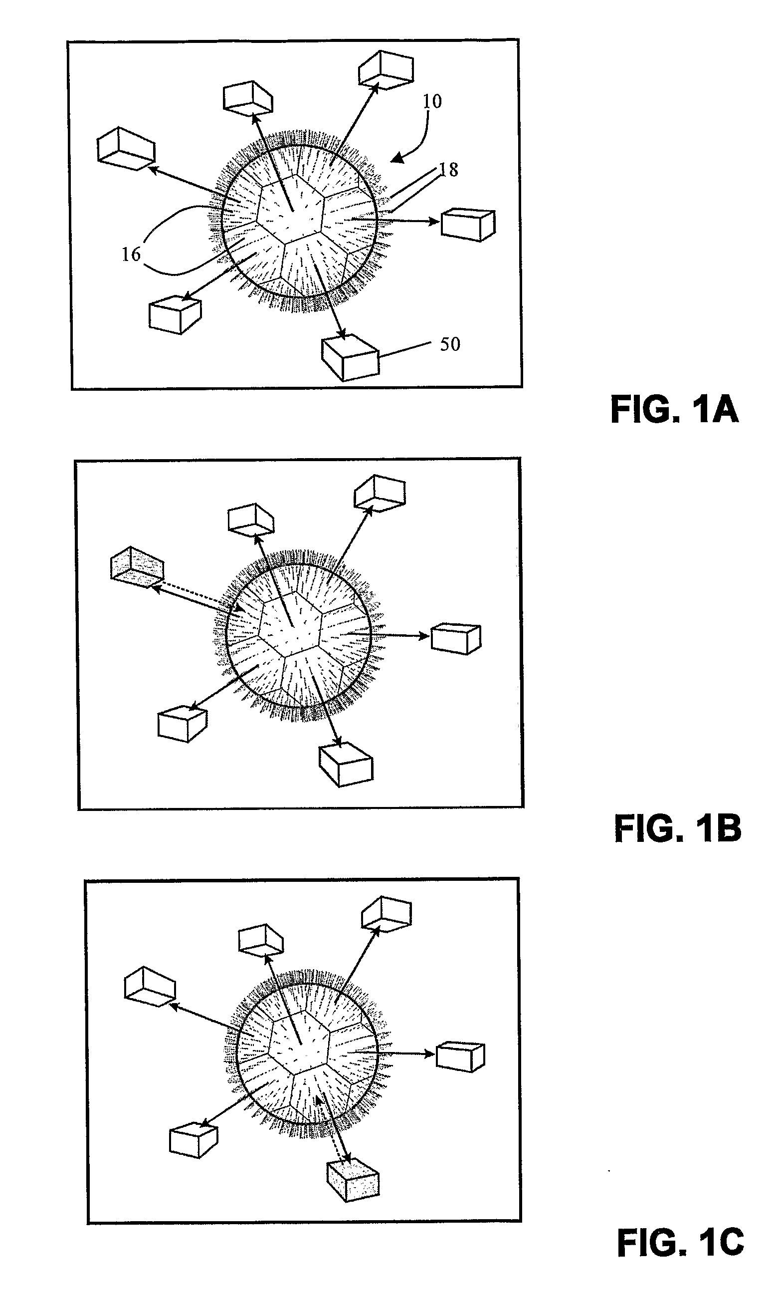
[0080] With reference to FIG. 1A, the base system of the present invention is now described.

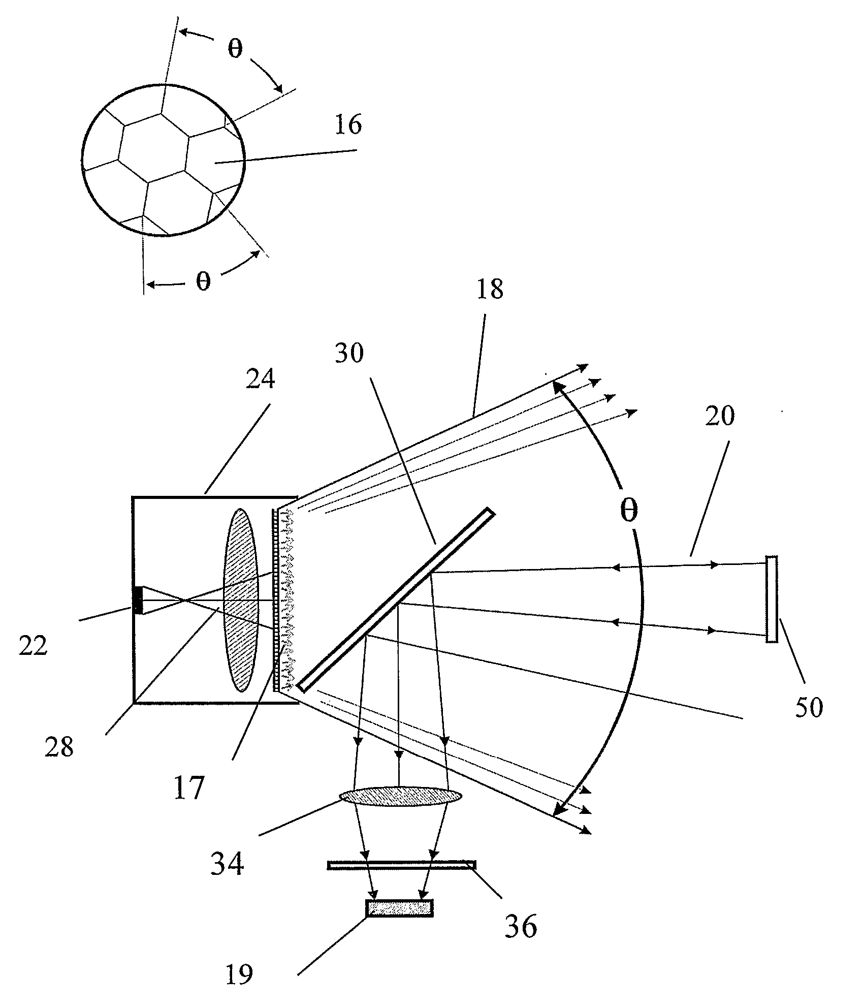
[0081] The base system comprises two primary units: transceiver unit 10 and retromodulator unit 50. Retromodulator unit 50 is capable of modulating a beam of radiant energy received from transceiver unit 10 with data and retroreflecting the modulated beam back to transceiver unit 10 where the data is demodulated from the beam, thereby resulting in data communication from the retromodulator unit 50 to the transceiver unit 10. Various novel applications are made possible by incorporating transceiver unit 10 into a device referred to herein as a data consumer and retromodulator unit 50 into a device referred to herein as a data producer.

[0082] A data consumer represents a device that uses a transceiver unit 10 to retrieve data from a retromodulator unit 50 on a data producer device.

[0083] Transceiver unit 10 comprises at least one of a plurality of segments. Each segment comprises a transceiv...


PUM


Abstract

A data communication system comprising a transceiver unit for retromodulated optical communication with at least one of a plurality of retromodulator units, the transceiver unit comprising at least one of a plurality of transceivers, the transceivers transmitting diffused radiant energy at different angles covering a predetermined three-dimensional area, wherein each transceiver is enabled to set up and execute communication with at least one retromodulator unit located within its coverage area. Furthermore, a retromodulator comprising multiple arrays of lenslets or spherically arranged lenslets is provided for achieving a wide angle of acceptance. Further more a number of novel applications based on the data communication system are provided, including a remote wireless network connection for a portable computing device, a smart card for remote wireless identification, remote data collection, and remote downloading of digital photographs.

Description

FIELD OF THE INVENTION [0001] The invention relates to retroreflecting optical communication, more particularly to low energy multidirectional optical communication wherein an incident beam is modulated with a signal and retroreflected to communicate the signal to the beam source. BACKGROUND OF THE INVENTION [0002] A retroreflector is an optical device that reflects an incident light beam back to the beam source. Light intensity modulators are a device that can change light transmission by applying electrical signals. Retromodulators combine these functions. Their use for communicating a signal by modulating the light beam with the signal is known. [0003] Examples of retromodulated optical communication between an optical transceiver unit and a mobile retromodulator unit are disclosed in a number of prior art patents. [0004] U.S. Pat. Nos. 4,731,879; 4,983,021; 5,909,299 are space applications. [0005] U.S. Pat. No. 6,154,299 describes a high repetition rate retromodulator. [0006] U....

Claims


Application Information

Patent Timeline
Patent Type & Authority Applications(United States)
IPC IPC(8): H04B10/00H04B10/26
CPCH04B10/2587H04B10/1121
Inventor KARASIKOV, NIRSLATKIN, MICHAELBEN-SHALOM, AMIRTAMIR, DAVID
Owner IRALINK
Learn More