Tissue harvesting device and method

a technology of dermal tissue and device, which is applied in the direction of shaping cutters, manufacturing tools, stock shearing machines, etc., can solve the problems of poor circulation, unclean wounds, and failure of grafts

Active Publication Date: 2007-08-02
KCI LICENSING INC
View PDF12 Cites 33 Cited by
  • Summary
  • Abstract
  • Description
  • Claims
  • Application Information

AI Technical Summary

Problems solved by technology

Factors that lead to graft failure include poor circulation, unclean wounds, patient interference with the graft dressing, obesity, and smoking.
Although such donor site infections are not likely related to graft failure at the wound site, they still pose problems for both the patient and caregiver.
While greater ratios of 9:1 and 12:1 may be possible using meshing techniques, there is also a significant delay in epithelialization with such ratios.
However, traditional techniques are cumbersome, and often the viability of the cells is compromised to such an extent that sometimes less than 50% of the cells are viable when applied to the wound site.
Additionally, traditional techniques have thus far been inadequate in producing viable cells in the range of 500-1500 microns.
However, disadvantages of using pieces larger than 1500 microns have been noted.
Among the disadvantages are that many of the cells are trapped within the pieces of skin, and are thus unable to proliferate or produce new cells required to form new skin.
This makes the procedure tedious and impractical.
Also, the appearance of the new skin that is produced using particles of this size is poor, often having a cobblestone appearance.
While sometimes producing cosmetically better grafts over the larger micrografts, many of the cells contained in the particles are rendered non-viable by the process of producing cells of such a small size.

Method used


Image

  • Tissue harvesting device and method
  • Tissue harvesting device and method
  • Tissue harvesting device and method

Examples


Embodiment Construction

[0030] Although those of ordinary skill in the art will readily recognize many alternative embodiments, especially in light of the illustrations provided herein, this detailed description is exemplary of the preferred embodiment of the present invention as well as alternate embodiments, the scope of which is limited only by the claims that may be drawn hereto.

[0031] Referring now to the drawings, the details of preferred embodiments of the present invention are graphically and schematically illustrated. Like elements in the drawings are represented by like numbers, and any similar elements are represented by like numbers with a different lower case letter suffix.

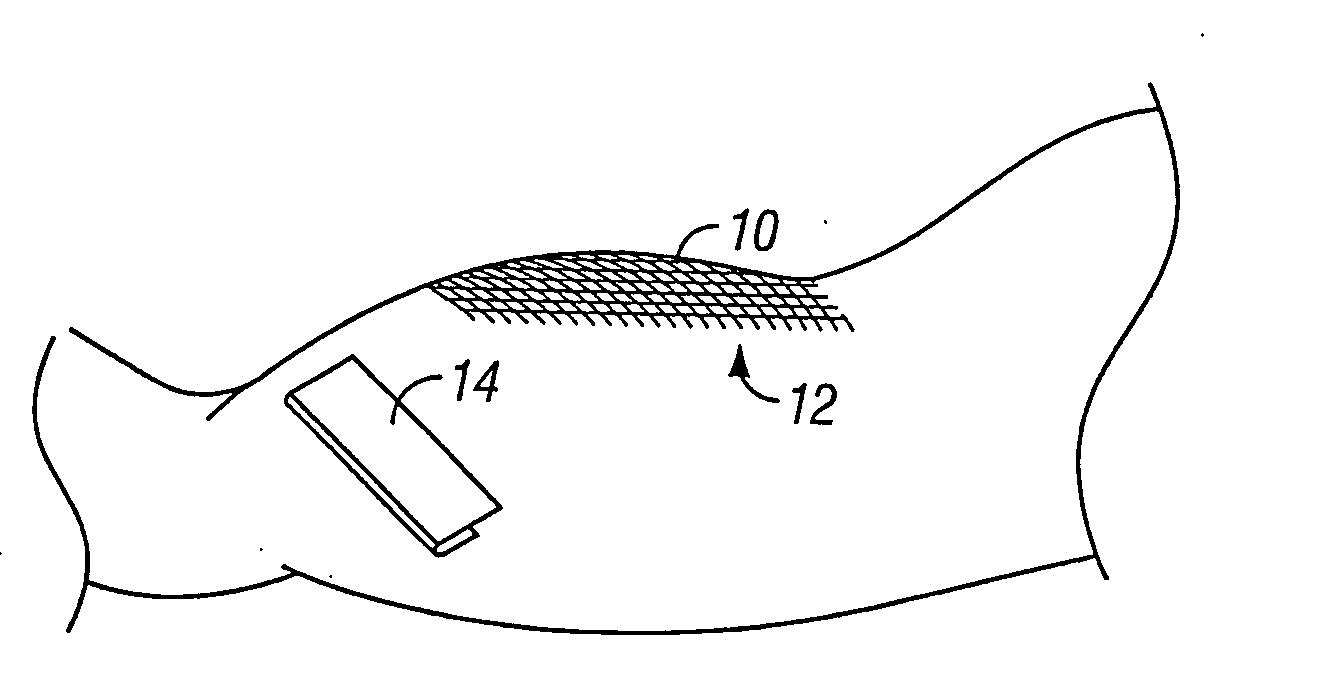
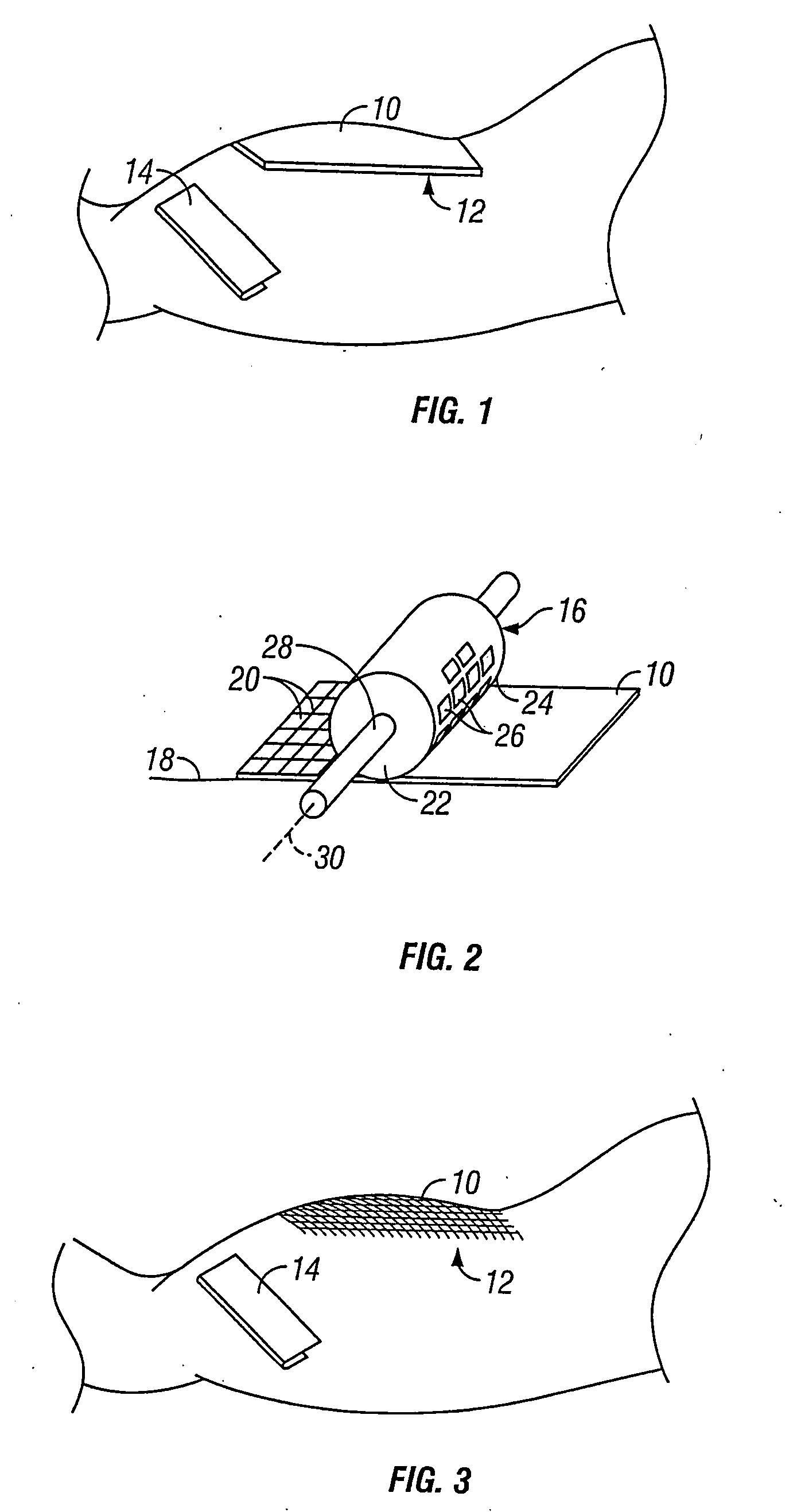
[0032] As illustrated in FIG. 1, a donor tissue sample 10, such as a split-thickness-skin graft (“STSG”) may be removed from a healthy region of skin tissue 12 using traditional techniques, such as by running a dermatome 14 across the surface of the donor site 12. The donor tissue 10 is positioned on a flat surface 18, so ...


PUM

PropertyMeasurementUnit
sizeaaaaaaaaaa
sizeaaaaaaaaaa
sizeaaaaaaaaaa

Abstract

A tissue harvesting method and device for obtaining micrograft tissue particles within the size range of 50-1500 microns, and more preferably 500-1000 microns, and most preferably 600 microns. The particles may be processed after a piece of donor tissue has been excised from the donor site, or processed into the desired size directly at the donor site, and thereafter excised. Cutters having blades or cutting edges spaced in the range of 50-1500 microns are utilized to obtain particles within the desired size range. An elastomer is positioned between the cutting edges to push the excised particles out of the blades for ease of use.

Description

CROSS-REFERENCE TO RELATED APPLICATION [0001] This is a division of co-pending application Ser. No. 10 / 442,488 entitled “Tissue Harvesting Device and Method,” filed May 21, 2003, which is a continuation-in-part of co-pending application Ser. No. 10 / 379,342 entitled, “Tissue Processing System,” filed Feb. 3, 2003; the prior applications are herewith incorporated by reference in their entirety.FIELD OF THE INVENTION [0002] The invention relates to a device and method for harvesting dermal tissue. More particularly, this invention relates to a device and method for extracting small particles of dermal tissue for transplantation to a recipient site. BACKGROUND OF THE INVENTION [0003] Traditional skin grafting is accomplished by taking a thin slice of dermal tissue from a donor site in order to cover a wound site, such as a burn area. In some instances, the slice of dermal tissue is meshed to expand its size, creating a meshed graft. Traditional devices used to harvest the tissue from th...

Claims


Application Information

Patent Timeline
Patent Type & Authority Applications(United States)
IPC IPC(8): A61B17/32A01N1/02A61BA61B1/00A61B17/00A61B17/14A61B17/24A61B17/322
CPCA61B17/322A61B2017/00969A61B2017/3225Y10T407/12Y10T408/89Y10T408/34Y10T407/19Y10T83/0207Y10T83/4766Y10T83/0481Y10T83/9372Y10T83/465Y10T83/483Y10T83/0586Y10T83/7876Y10T83/0215Y10T83/748Y10T83/768Y10T83/788Y10T83/9498Y10T83/0524Y10T83/4795Y10T83/7809Y10T83/0515
Inventor MISHRA, AJITSEEGERT, CHARLESOHIRA, MAKOTO
Owner KCI LICENSING INC
Why Eureka
Try Eureka