
Thermal therapy device

a technology of thermal therapy and drive signal, which is applied in the field of thermal therapy device, can solve the problems of inability to generate with certainty a drive signal such as a switching frequency as to follow the varying resonance frequency, and the magnetic field generating device described above cannot be applied

Inactive Publication Date: 2007-08-02
KANAZAWA UNIV +1
View PDF2 Cites 26 Cited by
  • Summary
  • Abstract
  • Description
  • Claims
  • Application Information

AI Technical Summary

Benefits of technology

[0009] The present invention is intended to provide a thermal therapy device that can follow with certainty changes in the resonance frequency even if the load variation ranges widely a

Problems solved by technology

With the use of the above described thermal therapy device in such a case, since the PLL unit of the thermal therapy device comprises an analog circuit, it is impossible to generate with certainty a drive signal of such a switching frequency as to follow the varying resonance frequency.
More specifically, the magnetic field generating device as described above cannot be applied if the load variation ranges widely and the resonance frequency varies significantly.

Method used


Image

  • Thermal therapy device
  • Thermal therapy device
  • Thermal therapy device

Examples


Embodiment Construction

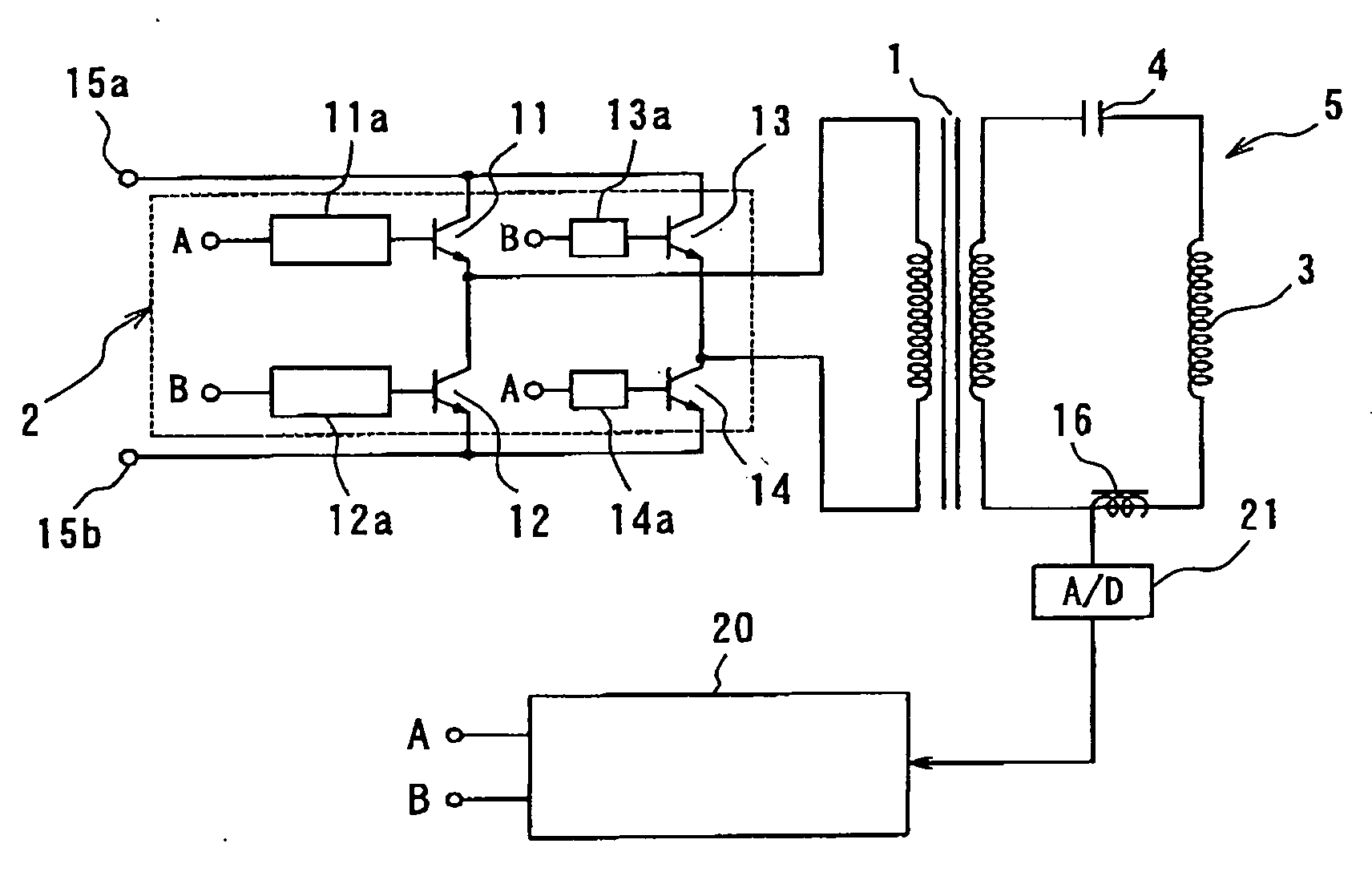
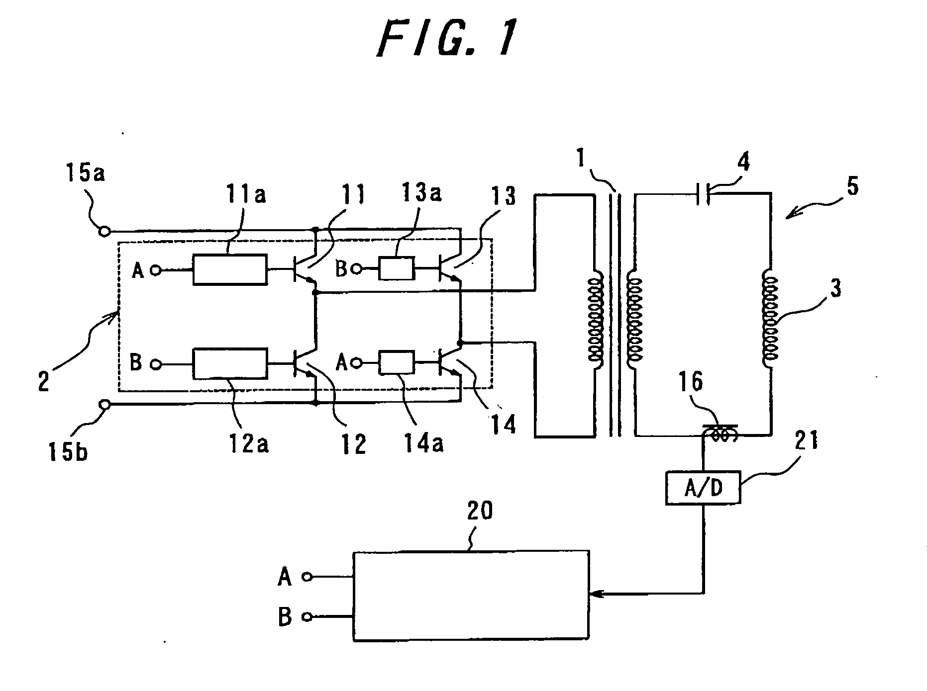
[0017]FIG. 1 is a constitution diagram showing an example of the thermal therapy device of the present invention. The thermal therapy device comprises a transformer 1, an inverter circuit 2 connected to the primary side of the transformer 1, a series resonance circuit 5 connected to the secondary side of the transformer 1, a current probe 16 for detecting a current passing in the series resonance circuit 5, an A / D converter 21 and a controller 20 for supplying a drive signal to the inverter circuit 2. The series resonance circuit 5 includes a magnetic field generation coil 3 and a resonance condenser 4. The inverter circuit 2 is an inverter circuit in the shape of an H-bridge and comprises four transistors 11 to 14 that operate as switching elements and four driver circuits 11a, 12a, 13a and 14a each driving each of the transistors 11 to 14 respectively. The inverter circuit 2 is provided with input terminals 15a and 15b which are applied with direct-current voltage.

[0018] The cont...


PUM


Abstract

There is provided a thermal therapy device that is capable of following changes in the resonance frequency even if the resonance frequency of the series resonance circuit on the secondary side changes significantly and generating a magnetic field of a required intensity for heating the affected portion. The thermal therapy device comprises an inverter circuit (2) connected to the primary side of a transformer (1), a series resonance circuit (5) connected to the secondary side of the transformer and including a magnetic field generation coil (3) and a resonance controller (4), and a controller (20) for determining the resonance frequency based on the secondary current. The therapy operation mode may be a measurement mode and an operation mode which are alternately repeated. During the measurement mode the resonance frequency of the series resonance circuit (5) is measured, while during the operation mode a drive signal of said measured resonance frequency is supplied from the controller (20) to the inverter circuit (2). Accordingly, the frequency of the drive signal to be supplied to the inverter circuit can follow the resonance frequency even if the impedance of the series resonance circuit (5) or the like varies during therapy.

Description

FIELD OF THE INVENTION [0001] The present invention relates to a thermal therapy device that selectively heats the patient's affected portion, particularly to a thermal therapy device that is useful for cancer therapy. BACKGROUND OF THE INVENTION [0002] The thermal therapy (hyperthermia) method is attracting attention as a method for cancer therapy. As for this thermal therapy method, attention is focused upon the fact that a cancer cell or a cancerous tissue is more vulnerable to heat than a healthy cell. By heating the cancer-affected portion for example to 43 degree C. for a certain length of time, the cancer lesion can selectedly be necrotized. In this thermal therapy method, an aqueous sol of magnetic fluid comprising a complex of dextran or its derivative and magnetic iron oxide, dextran magnetite for example, is injected into the affected portion, to which a strong magnetic field is applied from outside to selectively heat the cancer lesion. [0003] In such a method for therap...

Claims


Application Information

Patent Timeline
IPC IPC(8): A61F7/00A61F7/12A61N1/40A61N2/00
CPCA61N1/406
Inventor NAGANO, ISAMUIGARASHI, KOUICHI
Owner KANAZAWA UNIV
Learn More