Distributed diagnostics architecture

a diagnostics and architecture technology, applied in the field of vehicles, can solve problems such as not being able to adopt a common obd system approach

Active Publication Date: 2007-08-02
ELECTRONICS DATA SYST CORP +1
View PDF8 Cites 81 Cited by
  • Summary
  • Abstract
  • Description
  • Claims
  • Application Information

AI Technical Summary

Problems solved by technology

Presently, there is not a common OBD system approach that is readily adaptable to vehicle with varying system configurations.

Method used


Image

  • Distributed diagnostics architecture
  • Distributed diagnostics architecture
  • Distributed diagnostics architecture

Examples


Embodiment Construction

[0019]The following description of the preferred embodiment is merely exemplary in nature and is in no way intended to limit the invention, its application, or uses. For purposes of clarity, the same reference numbers will be used in the drawings to identify similar elements. As used herein, the term module refers to an application specific integrated circuit (ASIC), an electronic circuit, a processor (shared, dedicated, or group) and memory that execute one or more software or firmware programs, a combinational logic circuit, and / or other suitable components that provide the described functionality. As used herein, the term standard on-board diagnostics (OBD) driving cycle refers to a driving cycle, during which diagnostics are performed on all systems of the vehicle.

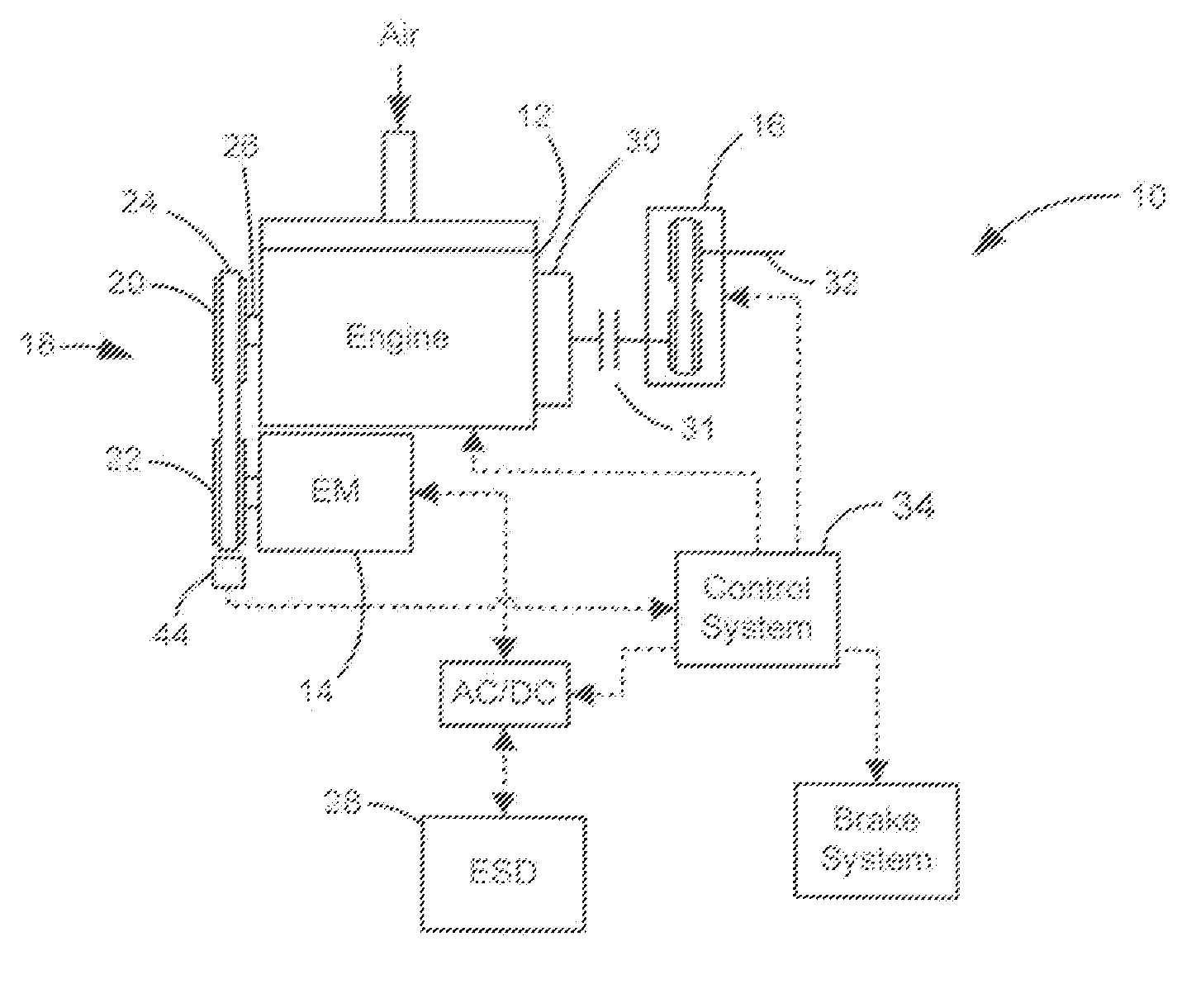
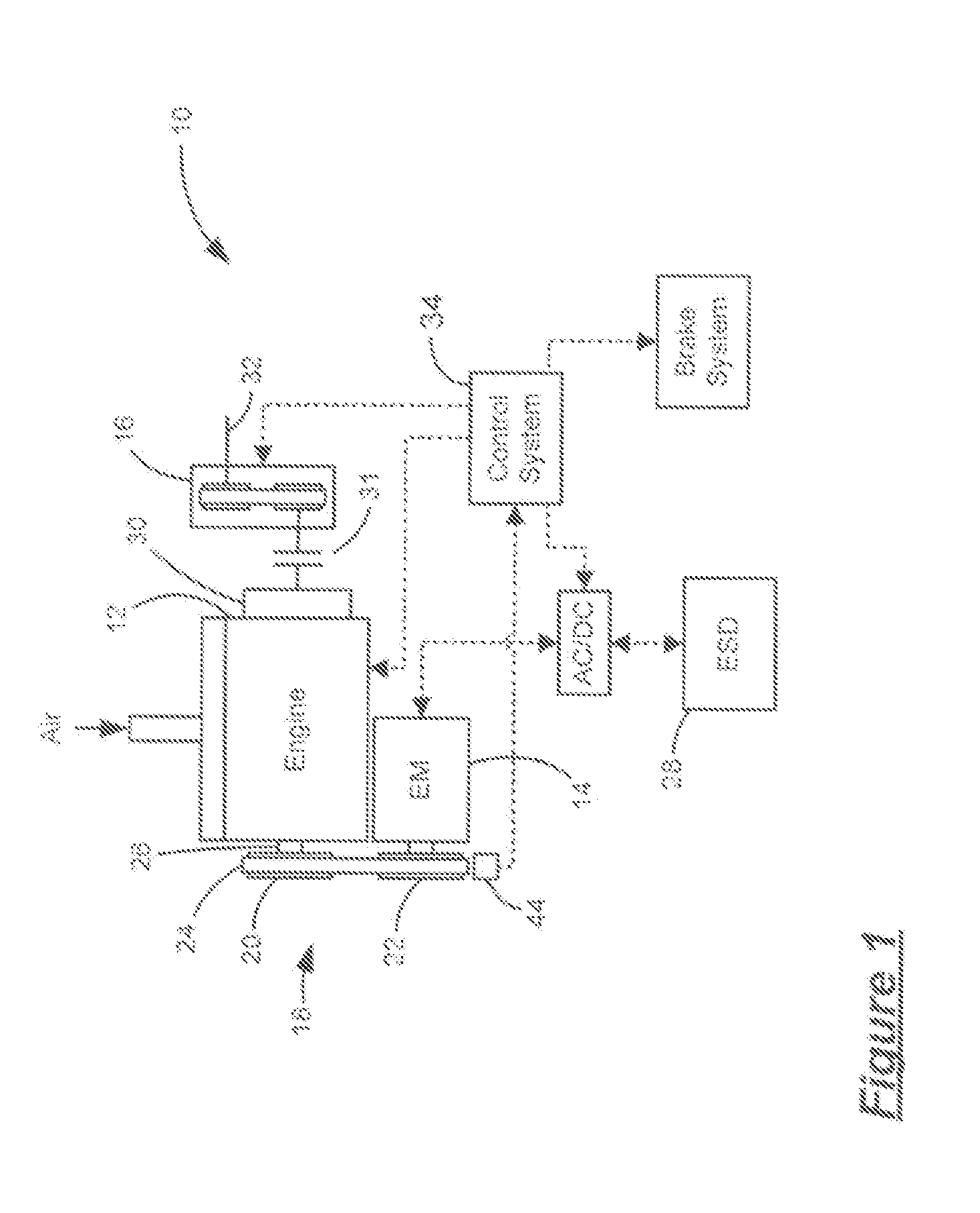
[0020]Referring now to FIG. 1, an exemplary hybrid vehicle 10 includes an engine 12 and an electric machine 14, which drive a transmission 16. More specifically, the electric machine 14 supplements the engine 12 to pro...


PUM


Abstract

A distributed on-board diagnostic (OBD) architecture for a control system of a vehicle includes a plurality of control modules that are in communication with one another and a designated master OBD control module that is one of the plurality of control modules. The master OBD control module performs functions that a remainder of the plurality of control modules are incapable of performing including at least one of arbitrating a malfunction indicator lamp (MIL) state, arbitrating and storing OBD freeze frame data and determining OBD status flags of the remainder of the plurality of control modules.

Description

CROSS-REFERENCE TO RELATED APPLICATIONS[0001]This application claims the benefit of U.S. Provisional Application No. 60 / 763,483, filed on Jan. 30, 2006.FIELD OF THE INVENTION[0002]The present invention relates to vehicles, and more particularly to a distributed diagnostics architecture for a vehicle including multiple control modules.BACKGROUND OF THE INVENTION[0003]Traditionally, vehicles include multiple systems that regulate overall operation of the vehicle. For example, the vehicle includes a power plant (e.g., an internal combustion engine and / or an electric machine) that generates drive torque, an energy storage device (e.g., battery pack) that provides electrical energy, a transmission that distributes the drive torque to drive wheels and various other systems. Each of the systems includes an associated control modules or modules that communicate with one another to regulate operation of the vehicle.[0004]Modern vehicles include an on-board diagnostic (OBD) system that provid...

Claims


Application Information

Patent Timeline
Patent Type & Authority Applications(United States)
IPC IPC(8): G01M17/00
CPCB60W50/029
Inventor GRENN, DANIEL P.WILMANOWICZ, MAREK L.KOTHARI, ANIKETWOZNIAK, LEONARD G.SCHROEDER, RICK H.ZETTEL, ANDREW M.WU, PETER E.WANG, WEI D.TALJONICK, MICHAEL J.PADMANABHAN, JAYANTHI
Owner ELECTRONICS DATA SYST CORP
Why Eureka
Try Eureka