Direct liquid fuel injection and ignition for a pulse detonation combustor

a pulse detonation combustible and liquid fuel injection technology, which is applied in the direction of intermittent jet plants, vessel construction, marine propulsion, etc., can solve the problems of increasing the overall cycle time and adversely affecting the generation of thrus

Inactive Publication Date: 2007-08-09
GENERAL ELECTRIC CO
View PDF12 Cites 29 Cited by
  • Summary
  • Abstract
  • Description
  • Claims
  • Application Information

AI Technical Summary

Problems solved by technology

The time scale of the fuel fill and the DDT process can be high for hydrocarbon-oxidizer mixtures, which can increase the overall cycle time, which in turn can adversely affect the generation of thrust.

Method used


Image

  • Direct liquid fuel injection and ignition for a pulse detonation combustor
  • Direct liquid fuel injection and ignition for a pulse detonation combustor
  • Direct liquid fuel injection and ignition for a pulse detonation combustor

Examples


Embodiment Construction

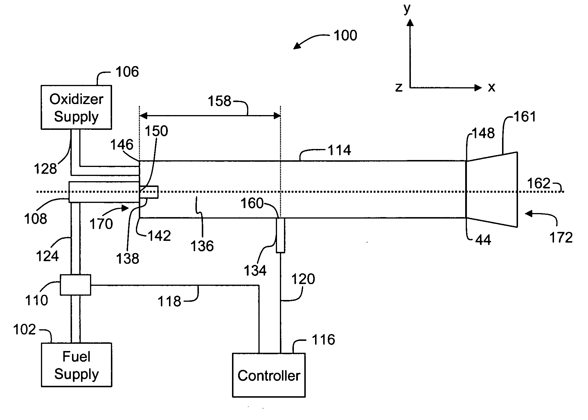
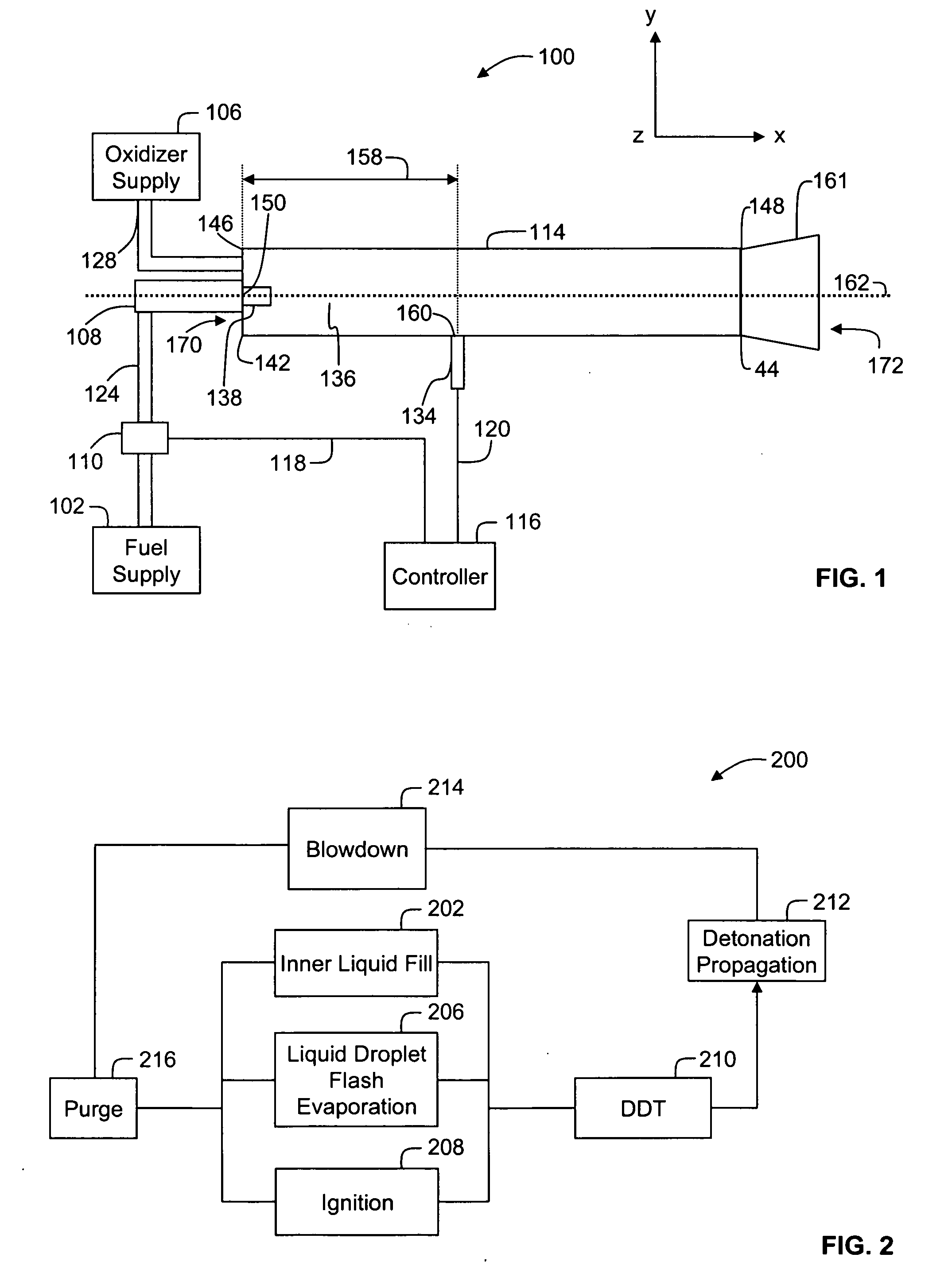
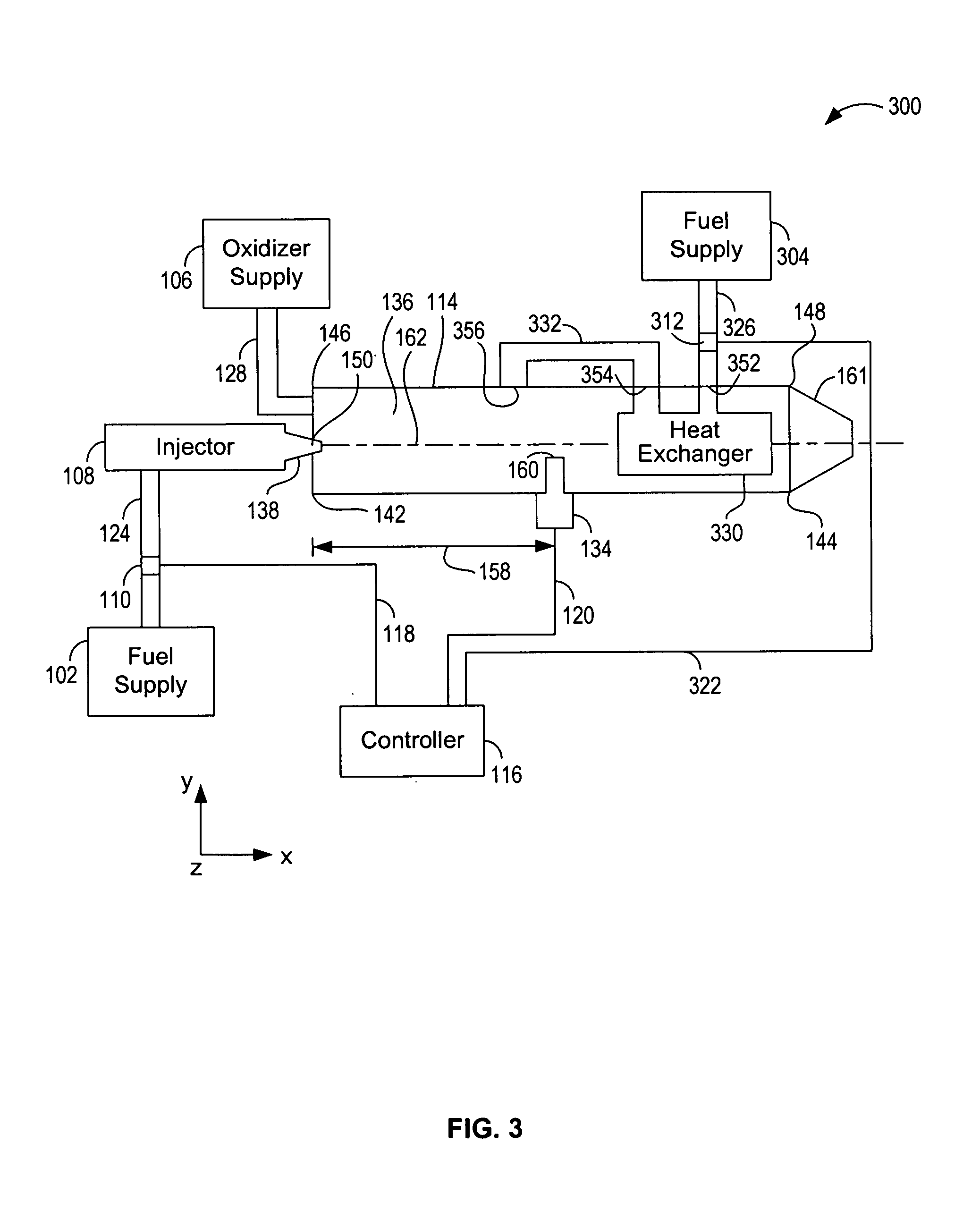
[0017] A pulse detonation combustor (PDC) includes a device or system that produces pressure rise, temperature rise and velocity increase from a series of repeating detonations or quasi-detonations within the PDC. In a flash vaporization process, the fuel pressure and temperature are above a critical point and hence when the fuel is injected via a pressure-assist atomizer into the PDC, which is at a lower pressure, the fuel flash vaporizes instantly there by decreasing the fuel evaporation time. An additional advantage of the flash vaporization process is improved mixing of the fuel and an oxidizer. A direct injection of a liquid fuel is performed when a plurality of liquid droplets are injected using a fuel injector downstream of any valves either on the fuel side or the oxidizer side and the fuel that is injected flows directly into the PDC. In addition, axial staging of the fuel and recirculation of heat from a plurality of walls of the PDC, and a provision to configure a preheat...


PUM


Abstract

A system for generating thrust is provided. The system includes a first injector, an inner tube configured to receive fuel from the first injector via a first port of the inner tube, where at least a portion of fuel in liquid phase received by the inner tube is configured to flash vaporize upon entering the inner tube via the first port.

Description

BACKGROUND OF THE INVENTION [0001] The present invention generally relates cyclic pulsed detonation combustors (PDCs) and more particularly, to two-phase fuel injection and ignition of fuel-oxidizer mixture to obtain reliable detonation initiations in the combustor. [0002] In a generalized pulse detonation combustor, fuel (vapor phase or liquid phase), and oxidizer (e.g., oxygen-containing gas) are admitted to an elongated combustion chamber at an upstream inlet end. An igniter is used to initiate this combustion process. Following a successful transition to detonation, a detonation wave propagates toward the outlet at supersonic speed causing substantial combustion of the fuel / oxidizer mixture before the mixture can be substantially driven from the outlet. The result of the combustion is to rapidly elevate pressure within the combustor before a substantial amount of gas can escape through the combustor exit. The effect of this inertial confinement is to produce near constant volume...

Claims


Application Information

Patent Timeline
Patent Type & Authority Applications(United States)
IPC IPC(8): F02K7/02
CPCF02K7/02
Inventor TANGIRALA, VENKAT ESWARLUHINCKLEY, KEVIN MICHAELCHAPIN, DAVID MICHAELDEAN, ANTHONY JOHN
Owner GENERAL ELECTRIC CO
Why Eureka
Try Eureka