
Conditioning device of the free cooling type

a technology of free cooling and conditioning device, which is applied in the direction of energy-efficient heating/cooling, heating types, lighting and heating apparatus, etc., can solve the problem of certain slowness in the outflow of warm air insid

Inactive Publication Date: 2007-08-09
EMERSON NETWORK POWER SRL
View PDF4 Cites 5 Cited by
  • Summary
  • Abstract
  • Description
  • Claims
  • Application Information

AI Technical Summary

Benefits of technology

[0018]The aim of the present invention is to provide a conditioning device of the free cooling type which is capable of obviating the drawbacks revealed by known types.
[0019]Within this aim, an object of the present invention is to provide a conditioning device which is capable of increasing the efficiency and effectiveness of the free cooling operating mode.
[0021]Another object of the present invention is to provide a conditioning device of the free cooling type which can be manufactured cheaply with known systems and technologies.

Problems solved by technology

Although these known conditioning devices are highly appreciated because of the saving on consumption that they can achieve, together with the quality of their climate control, in the free cooling operating mode they typically have a certain slowness in the outflow of warm air inside the enclosed space, due both to the relatively convoluted path that said warm air must follow to arrive outside and because it is pushed outward only by the pressure determined by the inflow of the air from the outside by means of the first fan and by its natural rise.

Method used


Image

  • Conditioning device of the free cooling type
  • Conditioning device of the free cooling type
  • Conditioning device of the free cooling type

Examples


Embodiment Construction

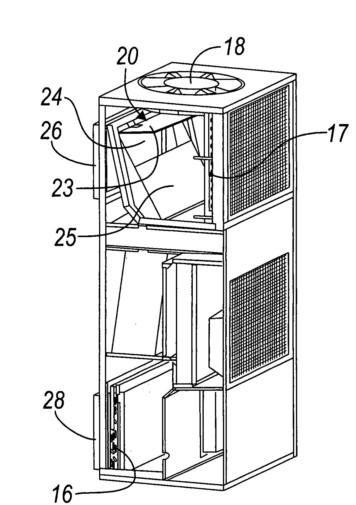
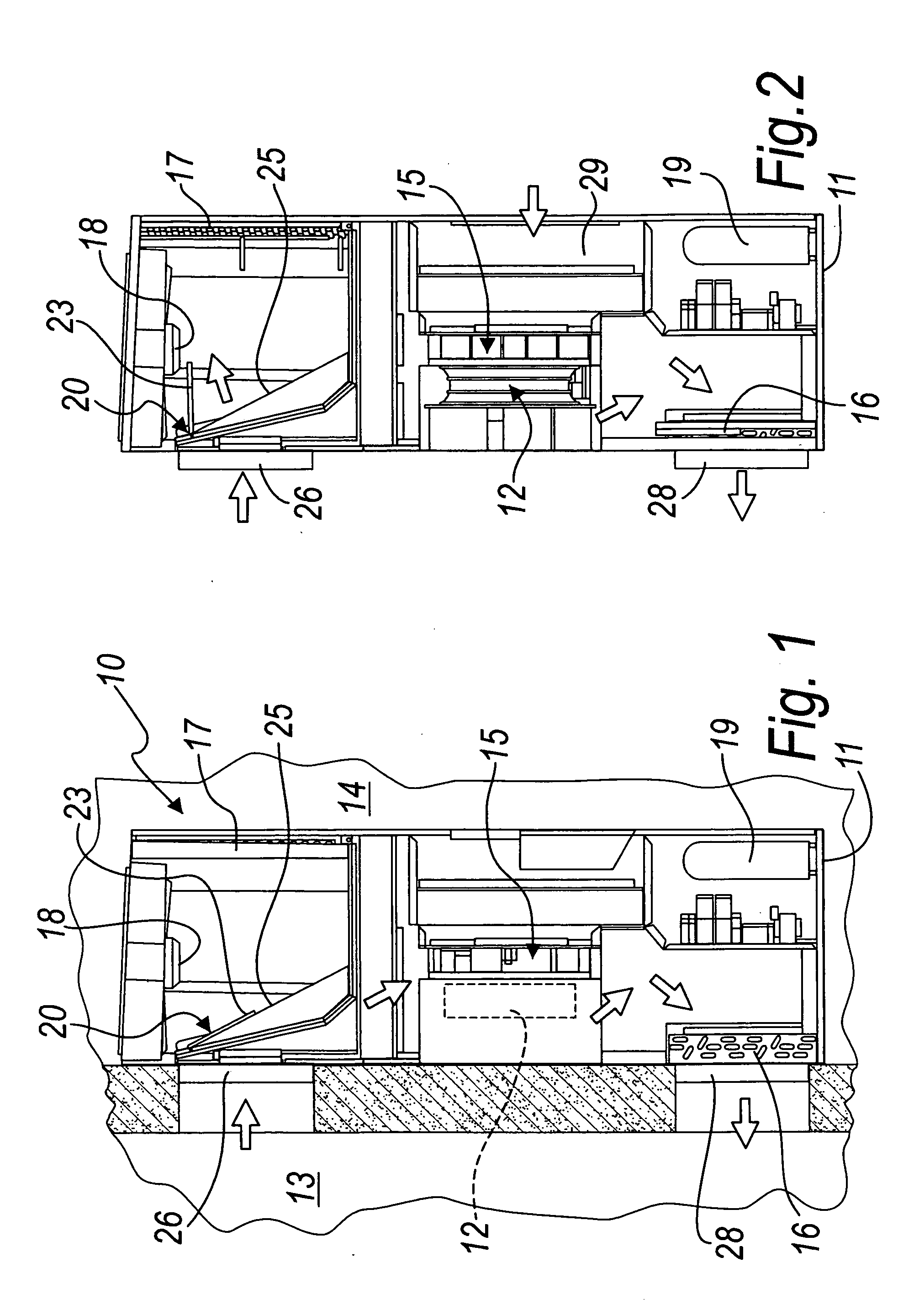
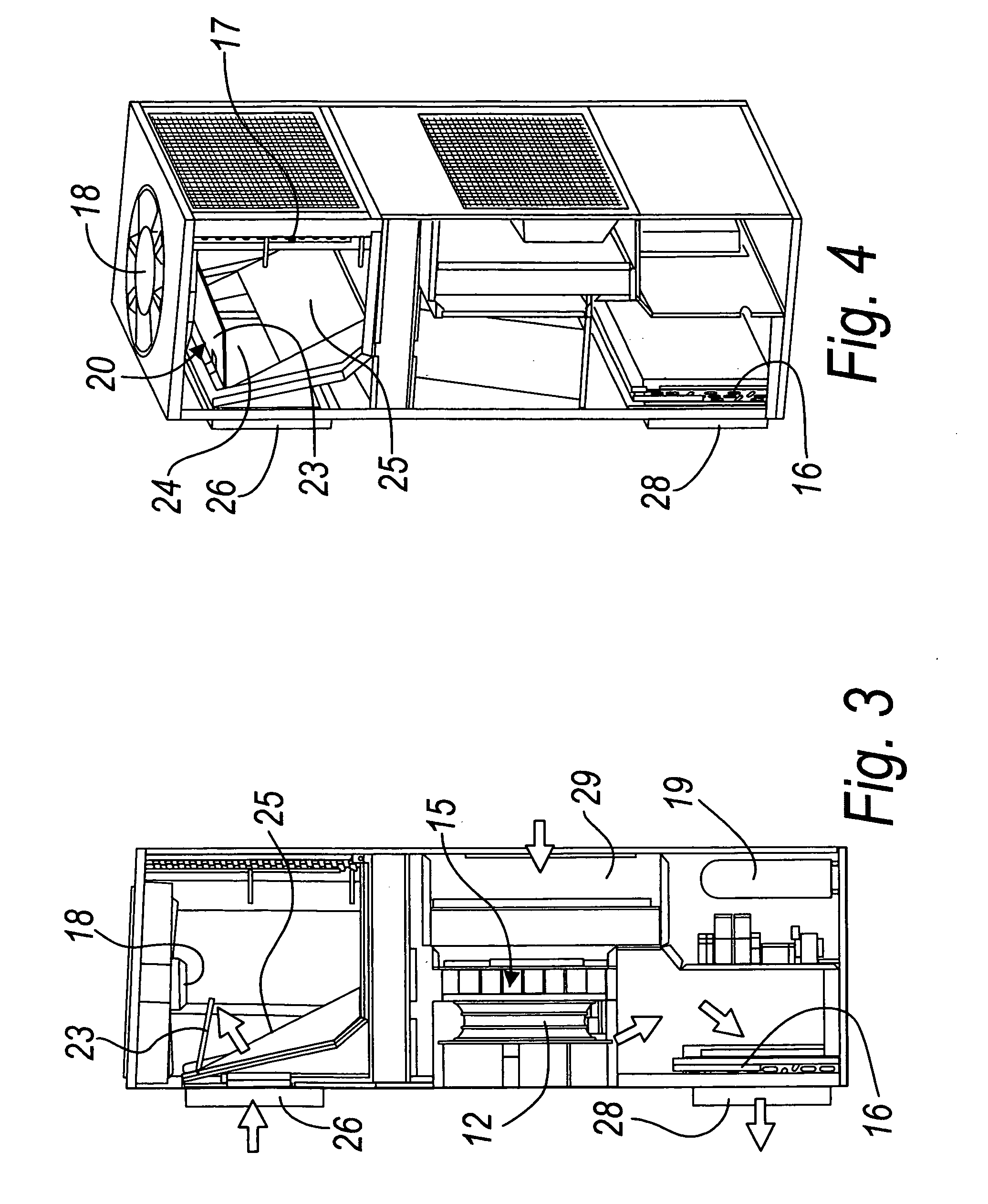
[0036]With reference to the figures, a conditioning device of the free cooling type according to the invention is generally designated by the reference numeral 10.

[0037]The conditioning device 10 comprises, within a box-like containment body 11:[0038]a first main fan 12 for aspirating air from the enclosed space 13 or from the outside 14;[0039]at least one shutter 15, upstream of the first fan 12, for selecting the air stream aspirated by the first fan 12: either ambient air for a first direct-cooling conditioning mode or external air for a second free cooling conditioning mode;[0040]an evaporator 16, to which the first fan 12 sends the aspirated air in order to introduce it in the enclosed space 13 to be climate-controlled;[0041]a condenser 17 associated or operatively connected with the evaporator 16;[0042]a second fan 18 for passing the flow of air over the condenser 17;[0043]a compressor 19, which is associated or operatively connected (i.e. connected for controlled, cooperating...


PUM


Abstract

A free cooling conditioning device for climate controlling of an enclosed space comprising, inside a box-like containment body, a first main fan for aspirating air from the enclosed / outside space, an evaporator, to which the first fan sends aspirated air to introduce it in the enclosed space, a condenser associated with the evaporator, a second fan for air flow over the condenser, a compressor, associated with the condenser and the evaporator to form a refrigeration circuit for aspirated air cooling, a first shutter, upstream of the first fan, for selecting the air stream aspirated by the first fan, from either ambient air, for a direct-cooling conditioning, or external air for free cooling conditioning, and a second shutter for redirecting the air stream in output from the enclosed space either toward the second fan, in the second free cooling mode, or toward the first shutter, at least partly open toward the first fan, for aspiration of ambient air, in the cooling mode.

Description

[0001]The present invention relates to a conditioning device of the free cooling type.BACKGROUND OF THE INVENTION[0002]Air conditioning devices provided with the option known as “free cooling” are currently known in the field of climate control of enclosed spaces ranging from industrial facilities to telephone exchanges to offices to private dwellings and the like.[0003]The free cooling option is based on the ability of the climate control unit to use, for the conditioning of an enclosed space, air which arrives from outside when said air has an enthalpy value which is higher than that of the air of the internal space.[0004]Free cooling allows considerable energy saving on the part of the user as well as a healthier management of the air of the internal space, which is replaced appropriately by activating free cooling.[0005]Known types of free cooling conditioning device are generally installed externally or are wall-mounted with respect to the walls which form the space to be clima...

Claims


Application Information

Patent Timeline
Patent Type & Authority Applications(United States)
IPC IPC(8): F25D17/04F25D17/06F24F1/02
CPCF24F1/027Y02B30/542F24F2011/0006F24F12/00Y02B30/54
Inventor LAZZARATO, MORENOBREGANTIN, MARISTELLALAZZARATO, MARCO
Owner EMERSON NETWORK POWER SRL
Learn More