Processing-fluid flow measuring method

Inactive Publication Date: 2007-08-09
TOKYO ELECTRON LTD
View PDF10 Cites 6 Cited by
  • Summary
  • Abstract
  • Description
  • Claims
  • Application Information

AI Technical Summary

Benefits of technology

[0008] The present invention has been made in view of the above circumstances. The object of the present invention is to accurately determine a flow rate of a process fluid such as a vapor, when an object to be processed such as a wafer is processed with the process fluid.
[0016] According to the above determining method and processing method, a flow rate of the process fluid or mixed fluid is determined based on a temperature of the process fluid or mixed fluid flowing through the supply pipe. Thus, even when the process fluid or mixed fluid includes bubbles or is in a gas phase, a flow rate thereof can be accurately determined. Since the process fluid or mixed fluid can be supplied into the process vessel at an accurate flow rate, improvement in process precision and improvement in reliability of a processing apparatus can be realized.
[0030] According to the above processing apparatuses, the controller monitors a flow rate of the process fluid or mixed fluid which is determined based on a temperature of the process fluid or mixed fluid detected by the temperature sensor. Thus, even when the process fluid or mixed fluid includes bubbles or is in a gas phase, a flow rate thereof can be accurately monitored while the process is performed. Since the process fluid or mixed fluid can be supplied into the process vessel at an accurate flow rate, improvement in process precision and improvement in reliability of a processing apparatus can be realized.
[0032] According to the present invention, even when the (second) process fluid is a vapor, a flow rate thereof can be accurately determined.

Problems solved by technology

Thus, a flow rate of a gas phase fluid cannot be determined.
However, detection of a flow rate of a vapor is impossible, when dew drops are formed.
Therefore, there has been a problem in that a flow rate of a process fluid, in particular, a vapor cannot be accurately determined by these ultrasonic flowmeter and flow meter.

Method used


Image

  • Processing-fluid flow measuring method
  • Processing-fluid flow measuring method
  • Processing-fluid flow measuring method

Examples


Embodiment Construction

[0039] An embodiment of the present invention will be described in detail below with reference to the accompanying drawings. Given herein as an example to describe the process with a process fluid is a case where a semiconductor wafer as an object to be processed is processed such that a resist on a surface of the semiconductor wafer is made soluble in water (ozone process).

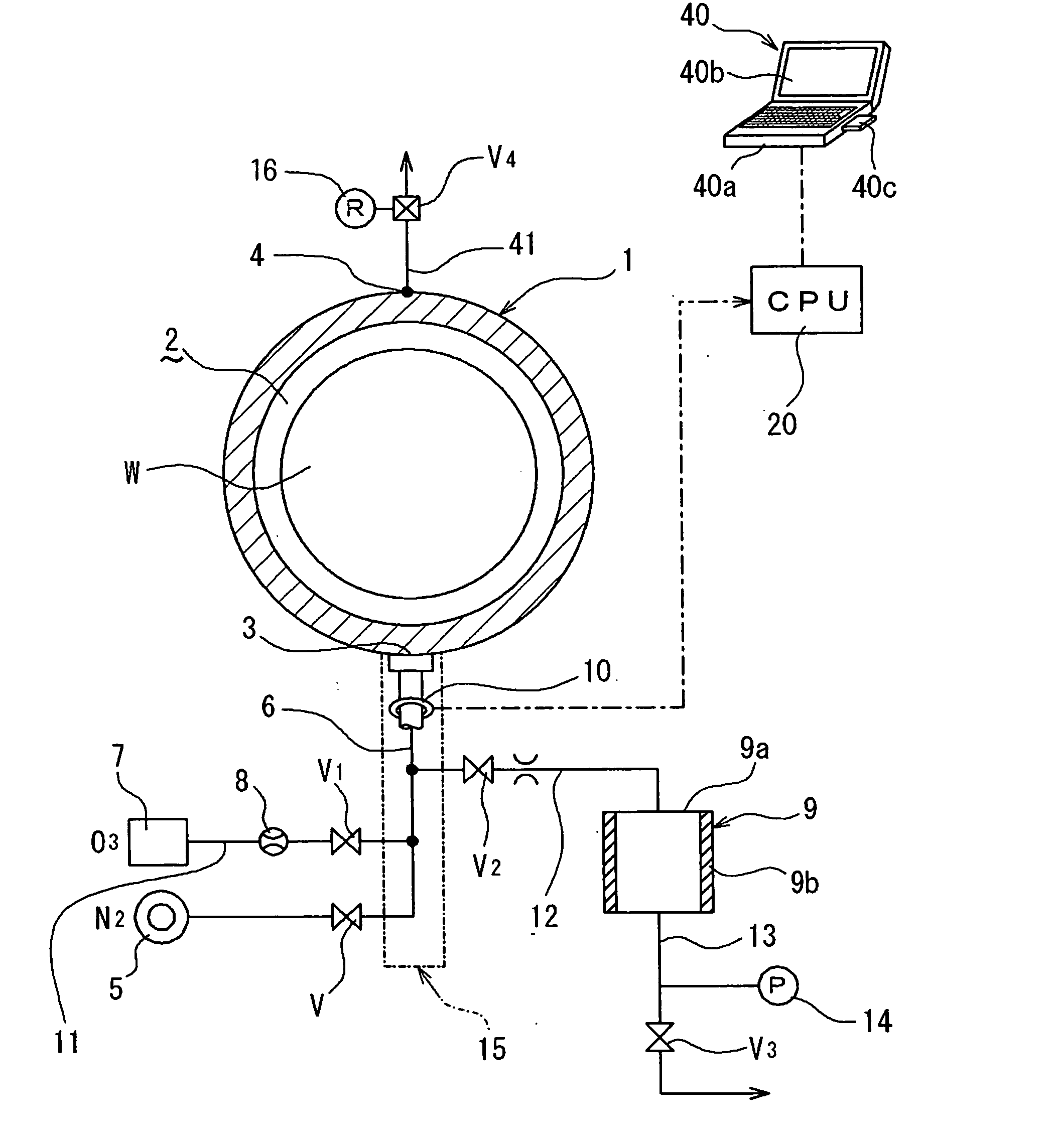
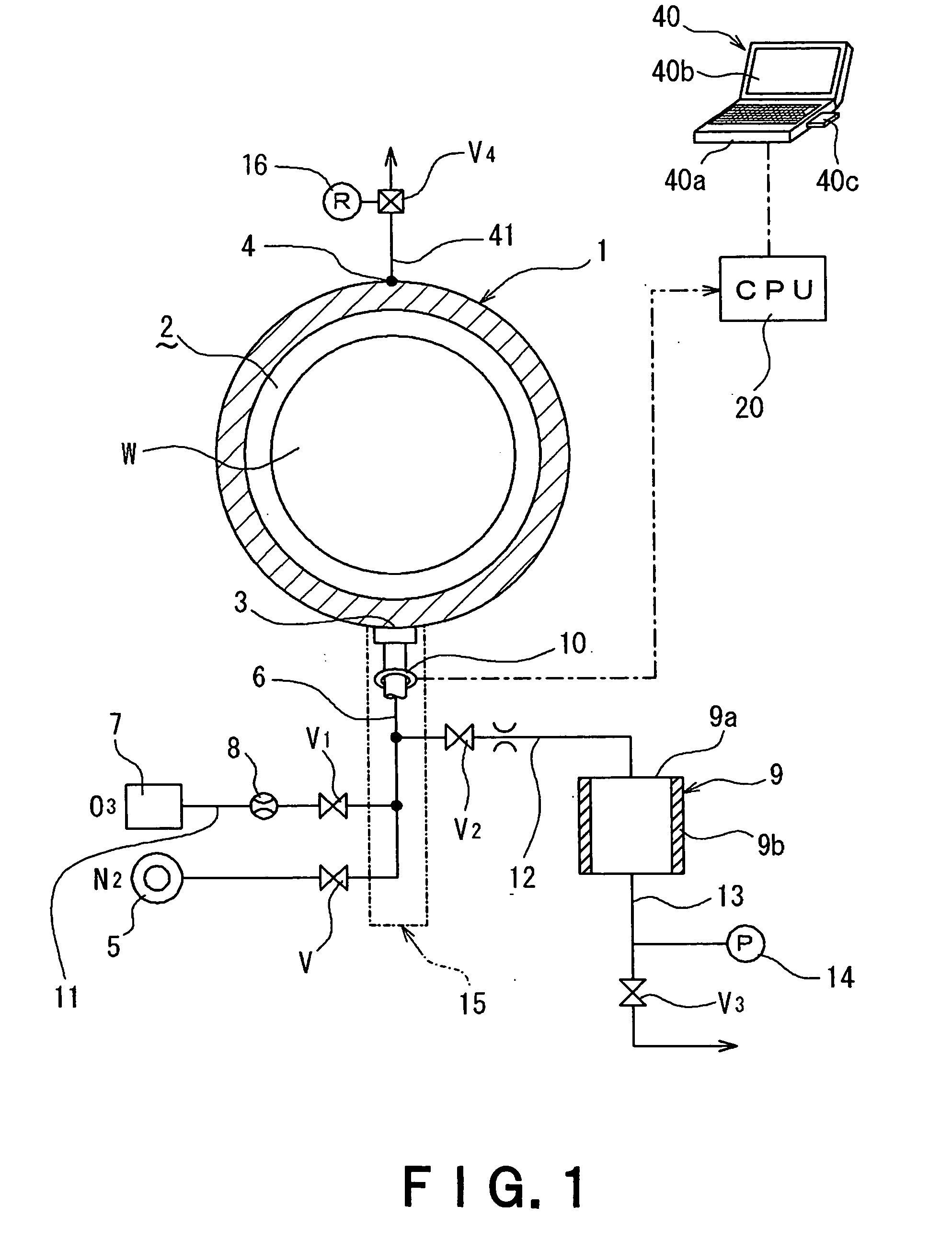
[0040] A processing apparatus shown in FIG. 1 includes a process vessel 1, a supply pipe 6, a supply source 5 of nitrogen (N2) gas, a supply source 7 of ozone gas, a supply source 9 of water vapor, a temperature sensor 10, and a computer 40 as a controller. The computer 40 is provided with a central processing unit (CPU) 20.

[0041] The substantially cylindrical process vessel 1 defines therein a process chamber 2 for receiving a semiconductor wafer W. The process vessel 1 has a supply port 3 through which a process fluid is supplied and a discharge port 4 through which the process fluid is discharged. The supply...


PUM

PropertyMeasurementUnit
Temperatureaaaaaaaaaa
Flow rateaaaaaaaaaa
Heataaaaaaaaaa

Abstract

An object to be processed such as a semiconductor wafer is processed by supplying a process fluid such as an ozone gas and a water vapor into a process vessel from a supply source through a supply pipe. During the process, a temperature of the process fluid flowing through the supply pipe is detected. By previously measuring and recording a relationship between a temperature of the process fluid and a flow rate of the process fluid, for example, a flow rate of the process fluid can be determined based on the detected temperature of the process fluid.

Description

BACKGROUND OF THE INVENTION [0001] 1. Field of the Invention [0002] The present invention relates to a technique for determining a flow rate of a process fluid, such as a vapor, when the process fluid is used for processing semiconductor wafers or the like. [0003] 2. Description of the Related Art [0004] Various process fluids including liquids, such as chemical liquids and cleaning liquids, gases, and vapors are generally used for processing objects to be processed, such as semiconductor wafers and LCD glass substrates (hereafter referred to as “wafers”). For example, a process fluid of a predetermined temperature is supplied into a process vessel at a predetermined flow rate for processing wafers accommodated in the process vessel. [0005] In these processes, ultrasonic flowmeters and flow meters have been conventionally used for determining a flow rate of a process fluid (see, for example, JP2002-151458A and JP10-2768A). [0006] In general, an ultrasonic flowmeter sends an ultrason...

Claims


Application Information

Patent Timeline
IPC IPC(8): B08B6/00B08B3/00B08B7/04
CPCG01F1/68H01L21/67253G01F1/6847G01F1/684
Inventor SATAKE, KEIGO
Owner TOKYO ELECTRON LTD
Why Eureka
Try Eureka