
Separation apparatus and method

a separation apparatus and separation chamber technology, applied in the direction of liquid separation, filtration circuits, filtration separation, etc., can solve the problems of not removing all particulate matter, system requires a more complex arrangement and chamber configuration, etc., to achieve the effect of maximising the retention of non-floating separated material

Inactive Publication Date: 2007-08-09
CHRISTOPHER GARY
View PDF21 Cites 2 Cited by
  • Summary
  • Abstract
  • Description
  • Claims
  • Application Information

AI Technical Summary

Benefits of technology

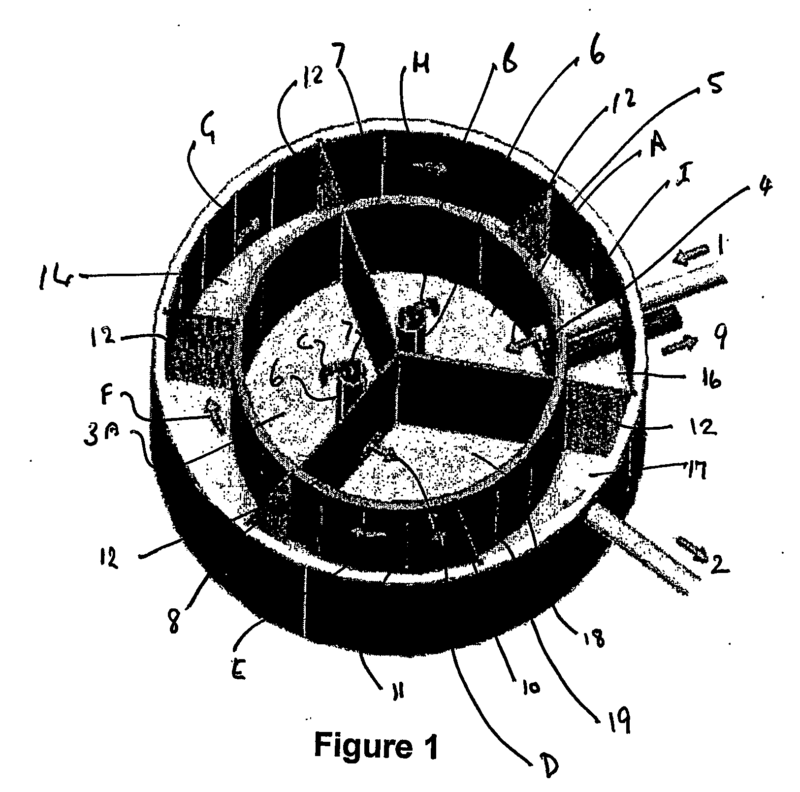
[0034] Preferably the two primary chambers are connected in series, the inlet to the apparatus feeding into a first of the primary chambers which is then connected to the second of the two primary chambers via one or more pipes configured in the nature of an inverted periscope skimmer to allow transfer of floating material from the first primary chamber to the second whilst maximising retention of non floating separated material.

Problems solved by technology

A number of the above described settling vessels can be used in series to maximise the particles removed from the liquid, however even this may not remove all particulate matter, especially where the remaining particles are relatively small (fines), and particularly where large flow volumes need to be treated.
Separation of components from liquids by electrostatic attraction has also been used, however this typically has the disadvantage that the system requires a more complex arrangement and chamber configuration in order to contain the separated components.

Method used


Image

  • Separation apparatus and method
  • Separation apparatus and method
  • Separation apparatus and method

Examples


Embodiment Construction

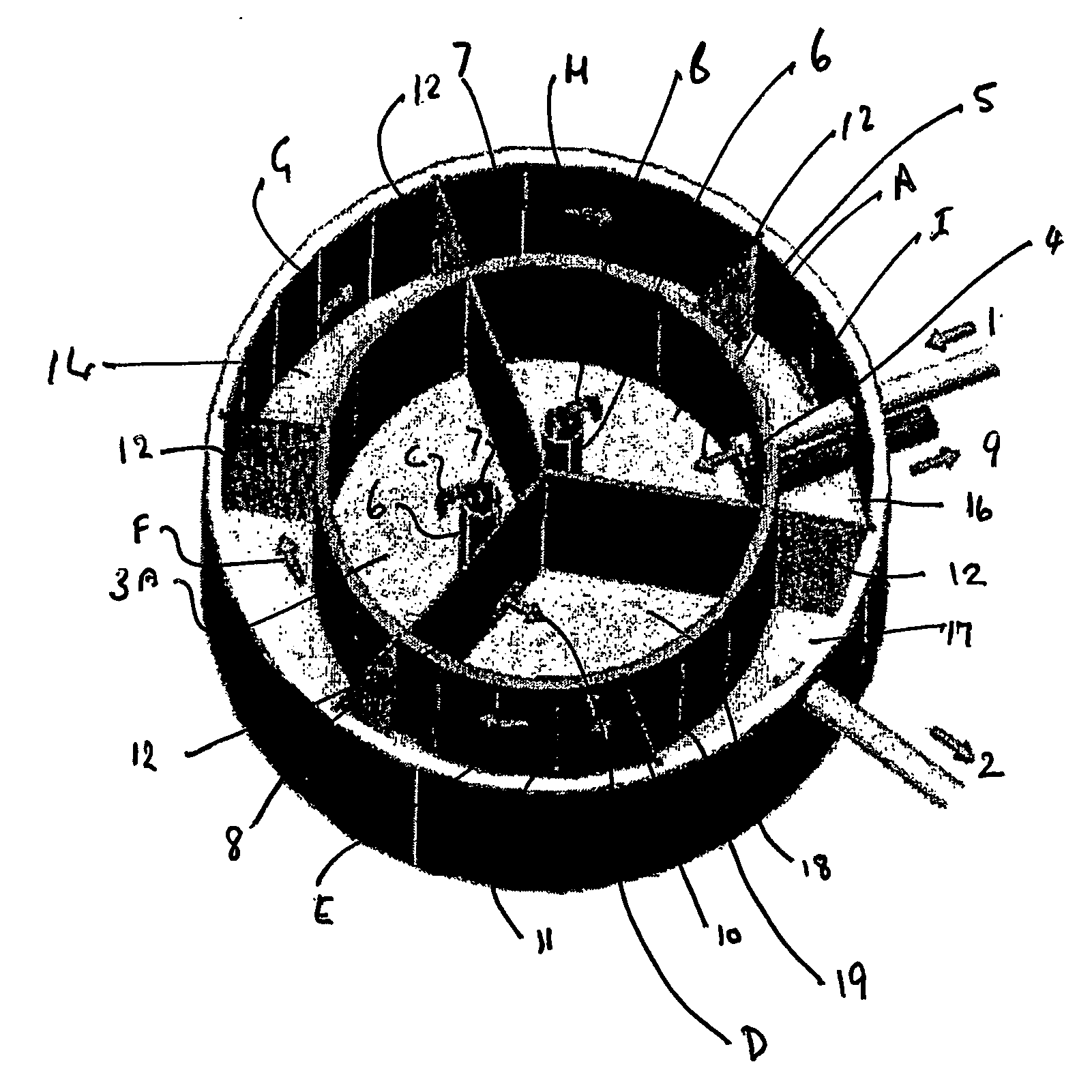
[0045] Separation apparatus configurations as shown in FIG. 1, or in FIGS. 3 and 4, may be utilised in order to separate materials (or contaminants) from a liquid for further use and / or treatment. In the drawings like components have been like numbered.

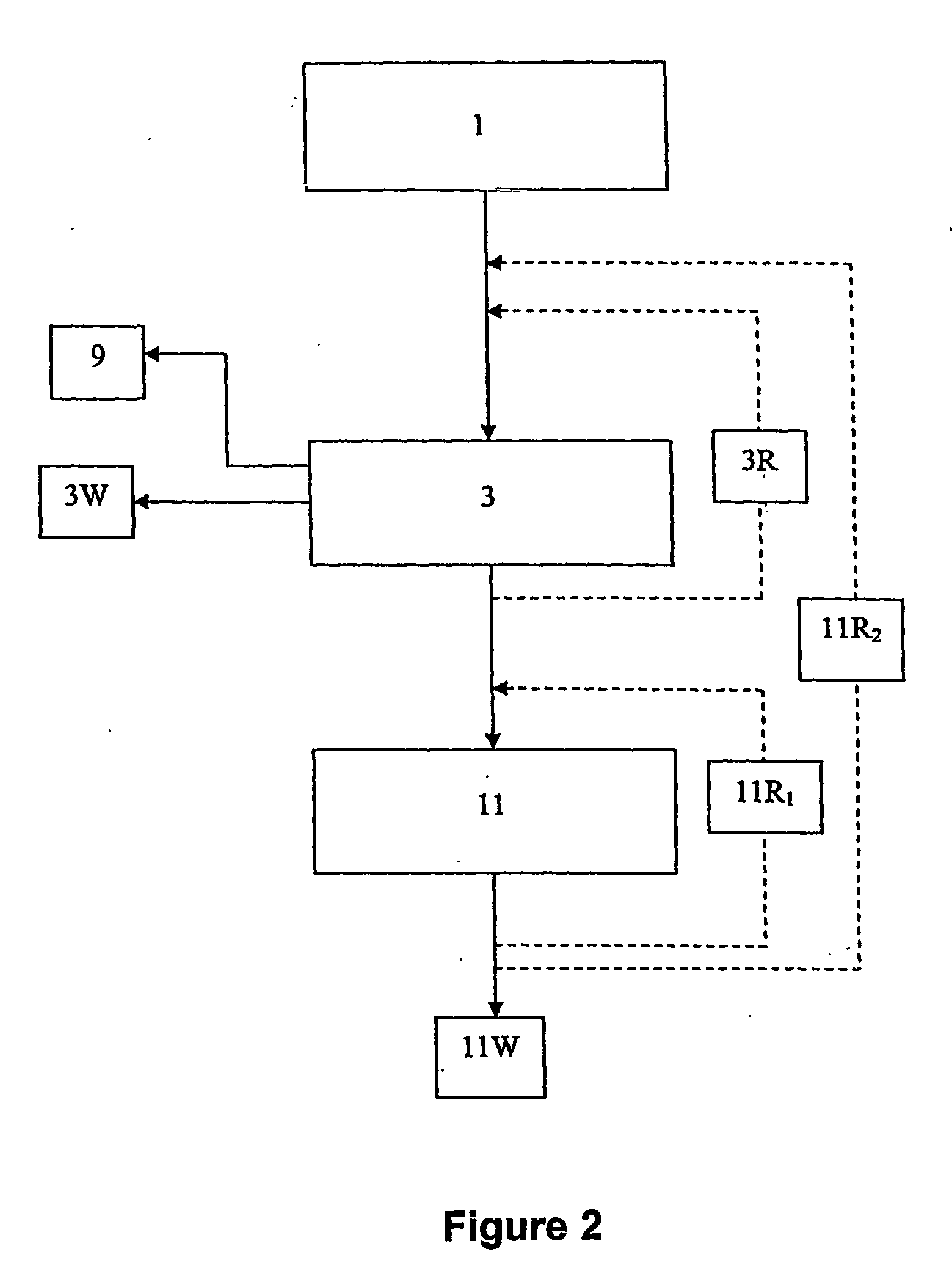
[0046] A process as outlined in FIG. 2 may be provided as a treatment process whereby a contaminated liquid input stream 1 fed into the process may result in a liquid output stream 2 including reduced contaminant matter.

[0047] Contaminants which may be entrained within the liquid feed 1 may be materials as are often found in typical run-off from road networks, airports, industrial operations or manufacturing processes and / or from municipal or industrial attachments or similar facilities. For example, this may also include run-off or spillage from bunded or dyked areas around the bases of reactor or storage vessels.

[0048] In order to help separate these sorts of materials from a liquid, the apparatus shown in FIG. 1 and / or the proce...


PUM

PropertyMeasurementUnit
sizesaaaaaaaaaa
adsorptionaaaaaaaaaa
gravityaaaaaaaaaa

Abstract

In its broadest aspect the invention provides apparatus for separation of contaminants from a liquid, said apparatus comprising a gravitational separation means (3) and a screen filter means (11), said screen filter means receiving output from said gravitation separation means (3), and wherein said screen filter (11) means includes woollen fibre.

Description

TECHNICAL FIELD [0001] This invention relates to separation of contaminants from a liquid, and in particular, though not solely, to an apparatus and process for this purpose. BACKGROUND ART [0002] Separation of materials from liquids is a relatively well explored and developed technical field in which improvements are continually being made. However, treatment systems are a constant ongoing subject of research and development in order attempt to refine the processes used to treat such liquids, with particular focus being on simplifying and reducing the associated treatment or pre-treatment costs. [0003] Treatment of liquids such as storm water run-off from road networks, airport runways, or industrial manufacturing operations, which may contain hydrocarbons (in particular petroleum hydrocarbons used within the transport industries), insoluble solids and / or heavy metals, is often required in order to meet the environmental discharge operating conditions and / or to alleviate the loadin...

Claims


Application Information

Patent Timeline
Patent Type & Authority Applications(United States)
IPC IPC(8): B01D12/00B01DB01D36/04B01D39/16
CPCB01D39/1615B01D36/04
Inventor CHRISTOPHER, GARY
Owner CHRISTOPHER GARY
Learn More