Facsimile servicing via peer-to-peer internet protocol telephony network

Inactive Publication Date: 2007-08-09
AVAGO TECH WIRELESS IP SINGAPORE PTE
View PDF15 Cites 7 Cited by
  • Summary
  • Abstract
  • Description
  • Claims
  • Application Information

AI Technical Summary

Problems solved by technology

When VoIP telephony was first introduced, the data packet transmission latency of the Internet and of other servicing networks caused the quality of VoIP telephony to be significantly worse than that of PSTN telephony.
Over time, packet data transmission latency of the Internet and of other servicing packet data networks has decreased.
However, only a limited number of people have a computer upon which this VoIP telephony application may be loaded and have Internet access of a quality that will support the VoIP telephony application.
VoIP telephony service providers typically extract a toll for servicing a call via the VoIP gateway bridge, thus destroying in part the low cost attractiveness of VoIP telephony.
The broadcast of FAX transmissions can be complex and costly.
Each of these facsimile transmissions co

Method used


Image

  • Facsimile servicing via peer-to-peer internet protocol telephony network
  • Facsimile servicing via peer-to-peer internet protocol telephony network
  • Facsimile servicing via peer-to-peer internet protocol telephony network

Examples


first embodiment

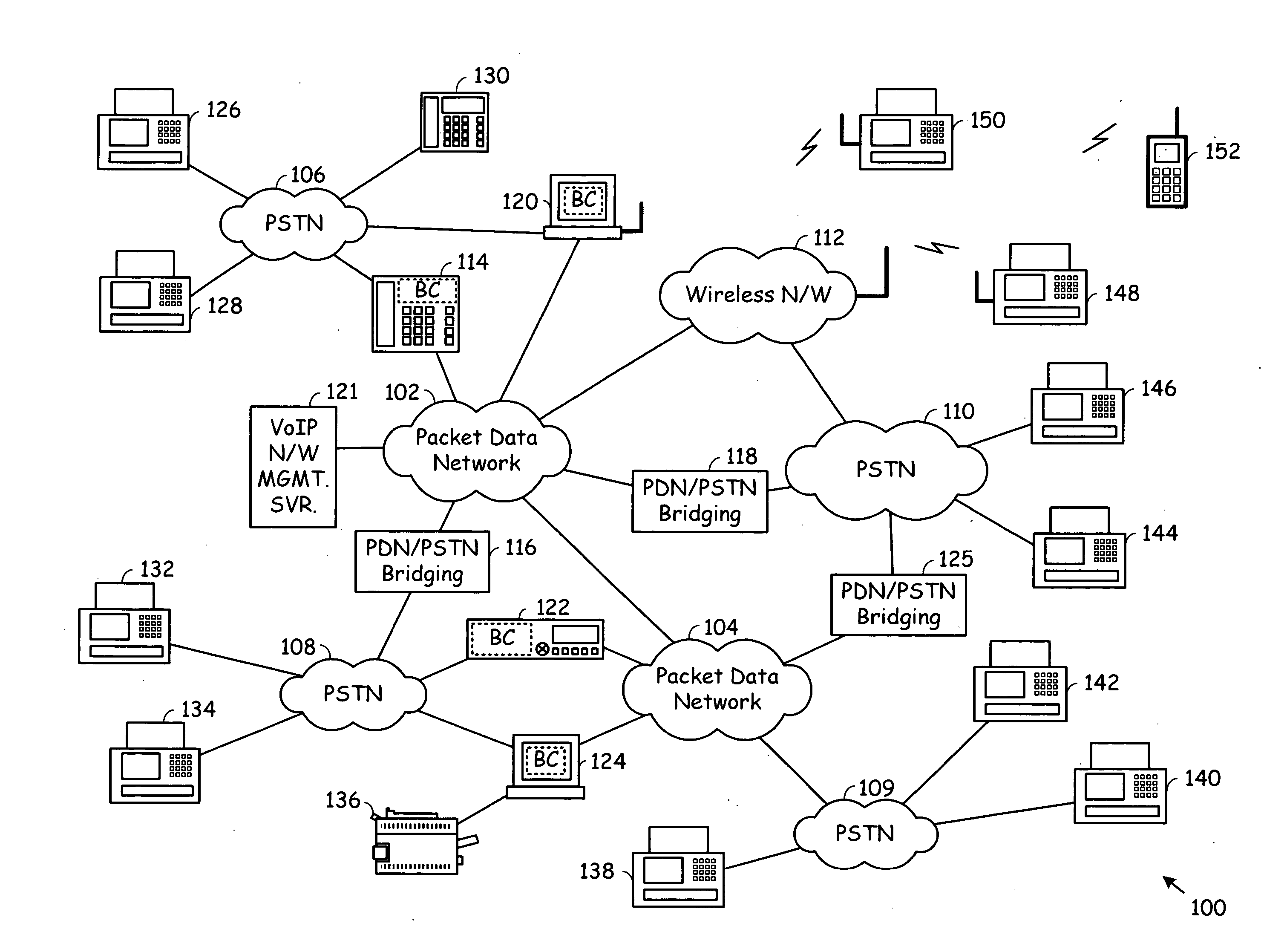
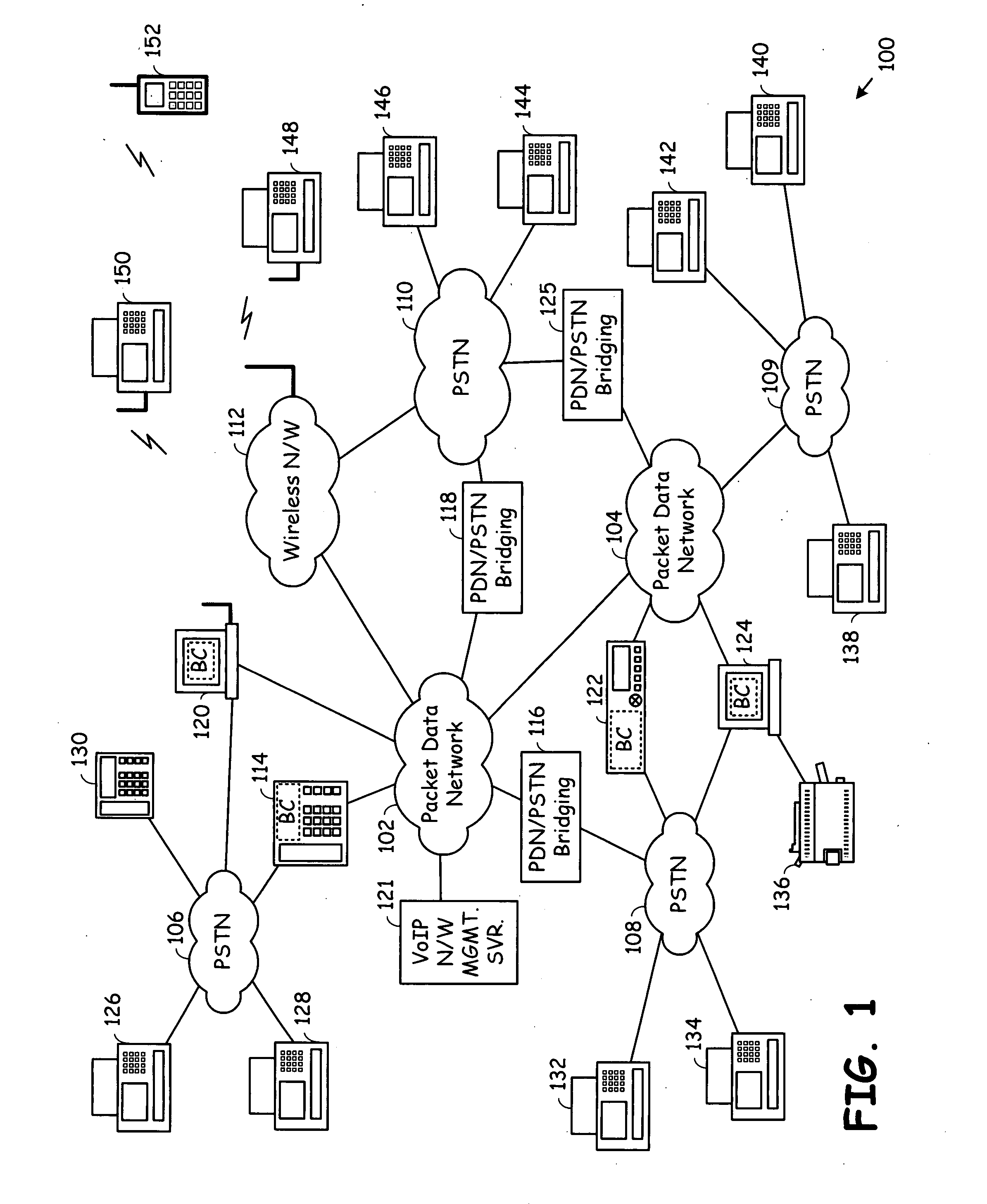
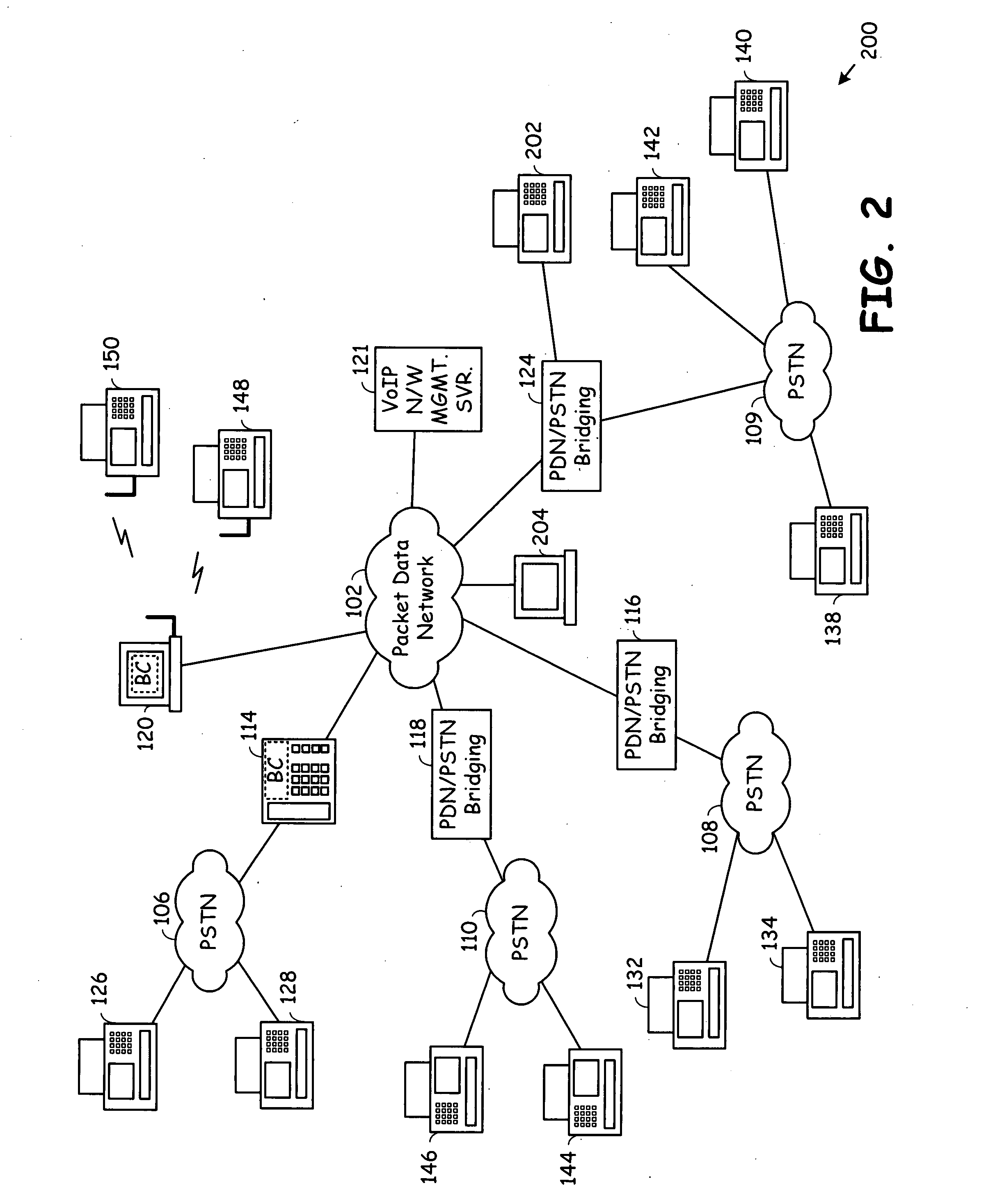
[0046]FIG. 3 is a flow chart illustrating a method for receiving FAX communications according to the present invention. Operation 300 commences with a source telephony bridging device receiving an incoming FAX communication via a source PSTN connection (Step 302). The incoming FAX communication has associated therewith an incoming FAX number. Then, based upon the incoming FAX number, a user ID and a peer-to-peer VoIP network is determined (Step 304). The source telephony bridging device may determine this user ID in the peer-to-peer VoIP network based upon access of a VoIP network management server 120, based upon access of local information, or a combination of these two operations.

[0047] Then, the source telephony bridging device determines an IP address of a destination telephony bridging device based upon the user ID in the peer-to-peer VoIP network (Step 306). The source telephony bridging device or the destination telephony bridging device may then determine an outgoing FAX nu...

second embodiment

[0048]FIGS. 4A and 4B are flow charts illustrating methods for receiving FAX communications according to the present invention. Referring to FIG. 4A, for each of a plurality of telephony bridging devices (Step 402), the source telephony bridging device receives an incoming FAX communication with an associated incoming FAX number (Step 404). The source telephony bridging device then determines a user ID in a servicing peer-to-peer VoIP network based upon the incoming FAX number (Step 406). Then, the source telephony bridging device and / or a management server of the VoIP network determines an IP address of a destination telephony bridging device based upon the user ID in the peer-to-peer VoIP network (Step 408). Then, the source telephony bridging device transmits the incoming FAX communication to the destination telephony bridging device (Step 410). Operations 404-410 are repeated for each of the plurality of source telephony bridging devices.

[0049] With reference to FIG. 4B, operati...


PUM


Abstract

Servicing an incoming Facsimile (FAX) communication includes receiving the incoming FAX communication by a source telephony bridging device via a source PSTN connection, the incoming FAX communication having an incoming FAX number associated therewith. Based upon the incoming FAX number, the source telephony bridging device determines a user ID in a peer-to-peer Voice over Internet Protocol (VOIP) network, determines an Internet Protocol (IP) address of a destination telephony bridging device based upon the user ID in the peer-to-peer VoIP network, and determines an outgoing FAX number based upon the user ID in the peer-to-peer VoIP network. The source telephony bridging device, an intermediate packet data network, and the destination telephony bridging device bridge the FAX communication from the source PSTN connection to a destination PSTN connection, the FAX communication directed to the outgoing FAX number.

Description

CROSS REFERENCES TO RELATED APPLICATIONS [0001] This application is a continuation-in-part of the following co-pending applications: [0002] 1. Utility application Ser. No. 11 / 348,962, filed on Feb. 7, 2006, and entitled “TELEPHONE SUPPORTING BRIDGING BETWEEN A PACKET SWITCHED NETWORK AND THE PUBLIC SWITCHED TELEPHONE NETWORK” (BP5090); [0003] 2. Utility application Ser. No. 11 / 348,814, filed on Feb. 7, 2006, and entitled “COMPUTING DEVICE SUPPORTING BRIDGING BETWEEN A PACKET SWITCHED NETWORK AND THE PUBLIC SWITCHED TELEPHONE NETWORK” (BP5092); [0004] 3. Utility application Ser. No. 11 / 348,743, filed on Feb. 7, 2006, and entitled “SET TOP BOX SUPPORTING BRIDGING BETWEEN A PACKET SWITCHED NETWORK AND THE PUBLIC SWITCHED TELEPHONE NETWORK” (BP5091); and [0005] 4. Utility application Ser. No. 11 / 448,458, filed on Jun. 6, 2006, and entitled “TELEPHONY BRIDGING DEVICE SUPPORTING MULTIPLE PATHWAY TELEPHONY BRIDGING” (BP5272), and [0006] 5. Utility application Ser. No. 11 / 641,196, filed on ...

Claims


Application Information

Patent Timeline
IPC IPC(8): H04L12/66
CPCH04M7/0063H04M2201/52H04M7/1235
Inventor BENNETT, JAMES D.
Owner AVAGO TECH WIRELESS IP SINGAPORE PTE
Why Eureka
Try Eureka