Method of channel estimation

Inactive Publication Date: 2007-08-09
HIMAX TECH LTD
View PDF9 Cites 14 Cited by
  • Summary
  • Abstract
  • Description
  • Claims
  • Application Information

AI Technical Summary

Benefits of technology

[0016]The invention is directed to a method of channel estim

Problems solved by technology

However, in the previously described channel estimation, it is necessary to estimate the channel response of each sub-channel in each time slot at the rec

Method used


Image

  • Method of channel estimation
  • Method of channel estimation
  • Method of channel estimation

Examples


Embodiment Construction

[0022]A traditional wireless receiver, such as a digital television receiver, has to timely estimate a channel response of the transmission channel due to its time-dependent variation, which thereby requires lots of resources and memory. However, in terms of a home use digital television receiver, the time-dependent variation of channel response is too small to be significant since the location of the TV set is fixed. By this feature, a method of channel estimation for a stationary wireless receiver is provided. The channel response is estimated only when some events occur, such as power on or degradation of signal quality. Only a small amount of resources and memory is required since the operation of channel estimation is simplified.

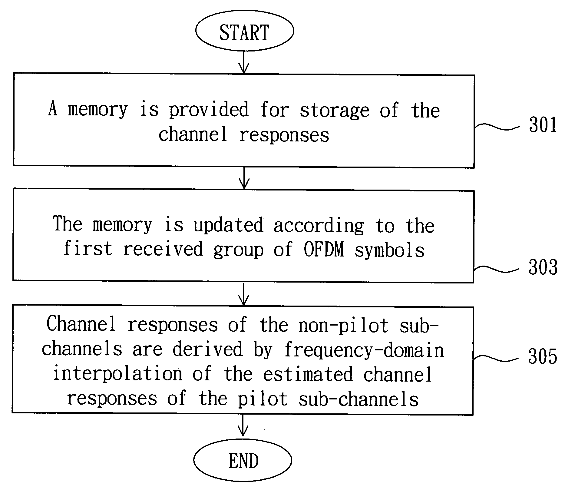
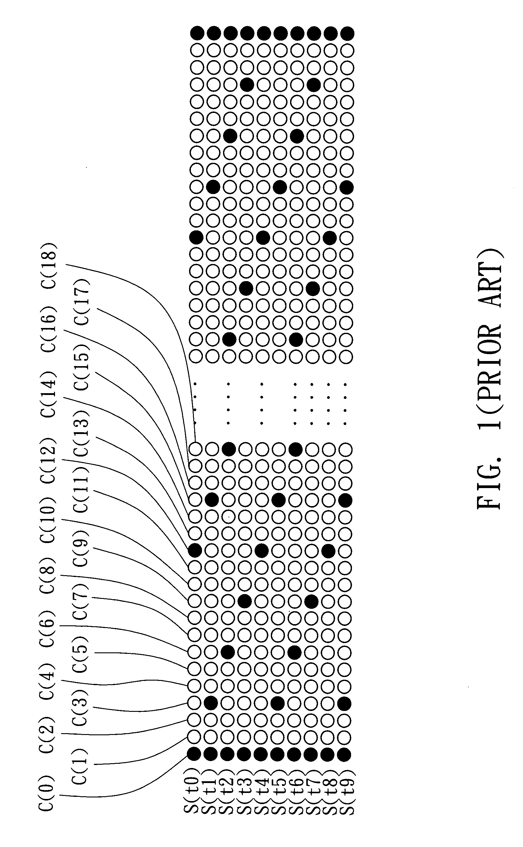
[0023]FIG. 3 is a flowchart of channel estimation according to a preferred embodiment of the invention. The pilot pattern used in the embodiment is the same as that in FIG. 1. Every four OFDM symbols, such as S(t0)˜S(t3), are arranged into a group. The ...


PUM


Abstract

A method of channel estimation is provided. The method is applied to a communication system having signals transmitted via a plurality of pilot and non-pilot sub-channels. The method comprises the steps of obtaining a first and second channel responses of each pilot sub-channel using pilot symbols received during a first and second time duration respectively, obtaining an estimated channel response of each pilot sub-channel by averaging the first and second channel responses thereof, and obtaining an estimated channel response of each non-pilot sub-channel by interpolation of those of the pilot sub-channels.

Description

[0001]This application claims the benefit of Taiwan application Serial No. 95104406, filed Feb. 9, 2006, the subject matter of which is incorporated herein by reference.BACKGROUND OF THE INVENTION[0002]1. Field of the Invention[0003]The invention relates in general to a method of channel estimation, and more particularly to a method of channel estimation which requires a small amount of memory and resources.[0004]2. Description of the Related Art[0005]The orthogonal frequency division multiplexing (OFDM) system having an advantage of preventing multi-path interference resulting in the ghost image is adopted by DVB-T (Digital Video Broadcast Terrestrial) for a high image quality.[0006]In the OFDM system, multi-carrier modulation is performed at the transmitter side and the data are transmitted on sub-carriers through a number of sub-channels. The sub-carriers have different frequencies and are orthogonal to each other such that the data are transmitted at a lower rate in each sub-cha...

Claims


Application Information

Patent Timeline
IPC IPC(8): H04K1/10H04L27/06
CPCH04L25/0226H04L25/0232H04L25/022H04L5/0048H04L5/0007
Inventor CHENG, SHIN-SHIUANWU, JU-CHUN
Owner HIMAX TECH LTD
Why Eureka
Try Eureka