Spin-orbit torque type magnetoresistance effect element, and method for producing spin-orbit torque type magnetoresistance effect element

a technology of spin-orbit torque and effect elements, which is applied in the direction of instruments, galvano-magnetic hall-effect devices, and record information storage, etc., can solve the problems of affecting the operation life of the element, affecting the overall amount of mram needed, and affecting the current amount of mram required. , to achieve the effect of higher outpu

Active Publication Date: 2018-05-03
TDK CORPARATION
View PDF5 Cites 6 Cited by
  • Summary
  • Abstract
  • Description
  • Claims
  • Application Information

AI Technical Summary

Benefits of technology

[0046]The magnetoresistance effect element 10 has a first ferromagnetic metal layer 1 having a fixed magnetization direction, a second ferromagnetic metal layer 2 having a variable magnetization direction, and a non-magnetic layer 3 sandwiched between the first ferromagnetic metal layer 1 and the second ferromagnetic metal layer 2.
[0047]The magnetoresistance effect element 10 functions by having the orientation of the magnetization M1 of the first ferromagnetic metal layer 1 fixed in a single direction, whereas the orientation of the magnetization M2 of the second ferromagnetic metal layer 2 is able to vary relatively. When applied to coercive force difference (pseudo spin valve) MRAM, the coercive force of the first ferromagnetic metal layer is larger than the coercive force of the second ferromagnetic metal layer, and when applied to exchange bias (spin valve) MRAM, the magnetization direction of the first ferromagnetic metal layer is fixed by exchange coupling with an antiferromagnetic layer.
[0048]When the non-magnetic layer 3 is formed from an insulator, the magnetoresistance effect element 10 is a tunneling magnetoresistance (TMR) element, whereas when the non-magnetic layer 3 is formed from a metal, the magnetoresistance effect element 10 is a giant magnetoresistance (GMR) element.
[0049]The stacking structure of the magnetoresistance effect element can employ a conventional magnetoresistance effect element stacking structure. For example, each layer may be composed of a plurality of layers, and the structure may also include other layers such as an antiferromagnetic layer for fixing the magnetization direction of the first ferromagnetic metal layer 1. The first ferromagnetic metal layer 1 is also called the fixed layer or reference layer, whereas the second ferromagnetic metal layer 2 is also called the free layer or the memory layer.
[0050]Conventional materials can be used as the material for the first ferromagnetic metal layer 1. For example, metals selected from the group consisting of Cr, Mn, Co, Fe and Ni, and alloys containing at least one of these metals and having ferromagnetism can be used. Further, alloys containing at least one of these metals and at least one element among B, C and N can also be used. Specific examples include Co—Fe and Co—Fe—B.
[0051]Further, in order to achieve higher output, a Heusler alloy such as Co2FeSi is preferably used. Heusler alloys contain intermetallic compounds having a chemical composition of X2YZ, wherein X is a noble metal element or a transition metal element belonging to the Co, Fe, Ni or Cu group of the periodic table, whereas Y is a transition metal belonging to the Mn, V, Cr or Ti group of the periodic table, and can select the elemental species of X, and Z is a typical element of group III to group V. Specific examples include Co2FeSi, Co2MnSi, and Co2Mn1-aFeaAlbSi1-b.

Problems solved by technology

However, if the current amount flowing through a single TMR element or GMR element is too large, the operating life of the element can be affected.
For example, the insulating layers of the TMR element may undergo insulation breakdown and the element may become incapable of recording data.
Additionally, if the current amount flowing through a single TMR element or GMR element becomes large, then the current amount necessary for the MRAM overall will also become large.

Method used


Image

  • Spin-orbit torque type magnetoresistance effect element, and method for producing spin-orbit torque type magnetoresistance effect element
  • Spin-orbit torque type magnetoresistance effect element, and method for producing spin-orbit torque type magnetoresistance effect element
  • Spin-orbit torque type magnetoresistance effect element, and method for producing spin-orbit torque type magnetoresistance effect element

Examples


Embodiment Construction

[0042]The present invention is described below in further detail, with reference to the drawings. The drawings used in the following description may be drawn with specific portions enlarged as appropriate to facilitate comprehension of the features of the present invention, and the dimensional ratios and the like between the constituent elements may differ from the actual values. Further, the materials and dimensions and the like presented in the following examples are merely examples, which in no way limit the present invention, and may be altered as appropriate within the scope of the present invention.

(Spin-Orbit Torque Type Magnetoresistance Effect Element)

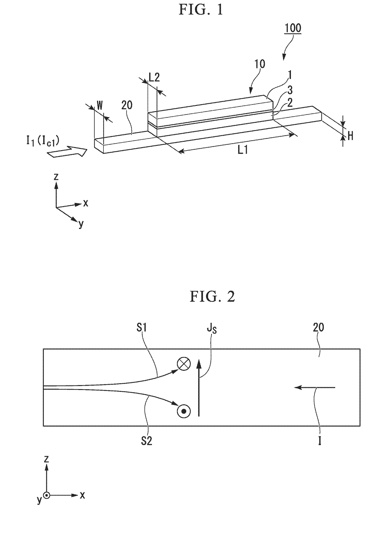
[0043]FIG. 1 is a perspective view schematically illustrating a spin-orbit torque type magnetoresistance effect element according to a first embodiment.

[0044]The spin-orbit torque type magnetoresistance effect element 100 according to the first embodiment has a magnetoresistance effect element 10 and spin-orbit torque wiring 2...


PUM


Abstract

A spin-orbit torque type magnetoresistance effect element including a magnetoresistance effect element having a first ferromagnetic metal layer with a fixed magnetization direction, a second ferromagnetic metal layer with a varying magnetization direction, and a non-magnetic layer sandwiched between the first ferromagnetic metal layer and the second ferromagnetic metal layer; and spin-orbit torque wiring that extends in a first direction intersecting with a stacking direction of the magnetoresistance effect element and that is joined to the second ferromagnetic metal layer; wherein the magnetization of the second ferromagnetic metal layer is oriented in the stacking direction of the magnetoresistance effect element; and the second ferromagnetic metal layer has shape anisotropy, such that a length along the first direction is greater than a length along a second direction orthogonal to the first direction and to the stacking direction.

Description

BACKGROUND OF THE INVENTIONField of the Invention[0001]The present invention relates to a spin-orbit torque type magnetoresistance effect element, and a method for producing a spin-orbit torque type magnetoresistance effect element. Priority is claimed on Japanese Patent Application No. 2016-210530, filed Oct. 27, 2016, and Japanese Patent Application No. 2017-138384, filed Jul. 14, 2017, the contents of which are incorporated herein by reference.Description of Related Art[0002]Examples of known magnetoresistance effect elements include giant magnetoresistance (GMR) elements composed of a multilayer film of ferromagnetic layers and non-magnetic layers, and tunnel magnetoresistance (TMR) elements which use insulating layers (tunnel barrier layers, barrier layers) for the non-magnetic layers. Generally, TMR elements have a larger element resistance than GMR elements, but the magnetoresistance (MR) ratio is larger than GMR elements. Consequently, TMR elements are attracting much attent...

Claims


Application Information

Patent Timeline
Patent Type & Authority Applications(United States)
IPC IPC(8): H01L43/06H01L43/04H01L43/12H01L43/10G11C11/16
CPCH01L43/065H01L43/04H01L43/12H01L43/10G11C11/161G11C11/1673G11C11/1675G11B5/3929H10N50/10H10N50/01G11C11/1659G11C11/18H10B61/22H10N50/80H10N52/101H10N50/85H10N52/80
Inventor SASAKI, TOMOYUKISHIOKAWA, YOHEI
Owner TDK CORPARATION
Why Eureka
Try Eureka