Magnetic powder and isotropic bonded magnet

a bonded magnet and magnetic powder technology, applied in the field of magnetic powder and isotropic bonded magnets, can solve the problems of low magnetic performance, insufficient magnetic flux density of conventional isotropic bonded magnets, and inability to achieve desired magnetic flux density, etc., to achieve excellent magnetic characteristics, large coercive force, and high magnetic characteristics

Inactive Publication Date: 2005-02-08
SEIKO EPSON CORP
View PDF38 Cites 0 Cited by
  • Summary
  • Abstract
  • Description
  • Claims
  • Application Information

AI Technical Summary

Benefits of technology

e bonded magnet high density. This advantage of the present invention can also be extended even in the case where bonded magnets are manufactured by the extrusion molding method or the injection molding method.
The content of the magnetic powder in the bonded magnet is not particularly limited, and it is normally determined by considering the compatibility of the molding method and moldability, and high magnetic characteristics. More specifically, it is preferable to be in the range of 75-99 wt %, and more preferably in the range of 85-97.5 wt %.
In particular, for a bonded magnet to be manufactured by the compression molding method, the content of the magnetic powder is preferable to be in the range of 90-99 wt %, and more preferably in the range of 93-98.5 wt %.
For a bonded magnet to be manufactured by the extrusion molding or the injection molding, the content of the magnetic powder is preferable to be in the range of 75-98 wt %, and more preferably in the range of 85-97 wt %.
The density ρ of the bonded magnet is determined by factors such as the specific gravity of the magnetic powder contained in the magnet and the content of the magnetic powder, and porosity of the bonded magnet and the like. In the bonded magnets according to this invention, the density ρ is not particularly limited, but it is preferable to be in the range of 5.3-6.6 g / cm3, and more preferably in the range of 5.5-6.4 g / cm3.
In this invention, since the magnetic flux density and the coercive force of the magnetic powder are high and the magnetic powder has a relatively larger coercive force, the molded bonded magnet provides excellent magnetic characteristics (especially, high maximum magnetic energy product) even when the content of the magnetic powder is relatively low. In this regard, it goes without saying that it is possible to obtain the excellent magnetic characteristics in the case where the content of the magnetic powder is high.

Problems solved by technology

Accordingly, when the magnetic performance (magnetization) of the magnetic powder itself is not sufficiently high, a desired magnetic flux density cannot be obtained unless the content of the magnetic powder in the bonded magnet is raised to an extremely high level.
On the other hand, however, the conventional isotropic bonded magnets such as those manufactured using MQP-B powder have the following disadvantages.(1) The conventional isotropic bonded magnets do not have sufficiently high magnetic flux density.
Specifically, because of the low magnetic performance (that is, the insufficient magnetization) of the magnetic powder used, the content of the magnetic powder to be contained in the bonded magnet has to be increased.
However, the increase in the content of the magnetic powder leads to the deterioration in the moldability of the bonded magnet, so there is a certain limit in this attempt.
Moreover, even if the content of the magnetic powder is somehow managed to be increased by changing the molding conditions or the like, there still exists a limit to the obtainable magnetic flux density.
For these reasons, it is not possible to reduce the size of the motor by using the conventional isotropic bonded magnets.(2) Since the conventional bonded magnet has high coercivity (coercive force), magnetizability thereof is poor, thus requiring a relatively high magnetic field for magnetization.(3) Although there are reports concerning nanocomposite magnets having high remanent magnetic flux densities, their coercive forces, on the contrary, are so small that the magnetic flux densities (for the permeance in the actual use) obtainable for the practical motors are very low.
Further, these magnets have poor heat stability due to their small coercive forces.(4) The conventional bonded magnets have low temperature characteristics (that, is heat resisting property or heat stability).
In particular, the irreversible flux loss remarkably drops when the coercive force (HCJ) is lowered.(5) The bonded magnet has poor corrosion resistance and heat resisting property.
Therefore, it is necessary to cover the outer surface of the bonded magnet with a coating, especially a resin coating which is capable of obtaining high corrosion resistance property, but this in turn leads to increased manufacturing cost and the presence of the resin layer results in lowered magnetic performance (this makes it difficult for a motor to generate a high torque).

Method used


Image

  • Magnetic powder and isotropic bonded magnet
  • Magnetic powder and isotropic bonded magnet
  • Magnetic powder and isotropic bonded magnet

Examples


example 1

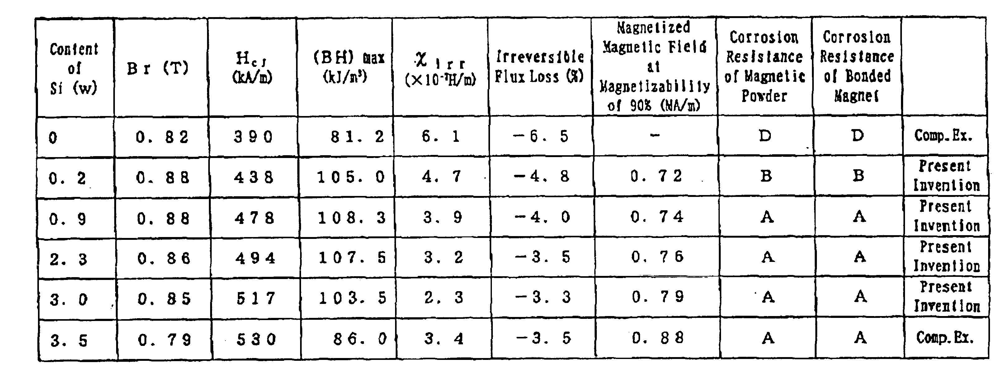
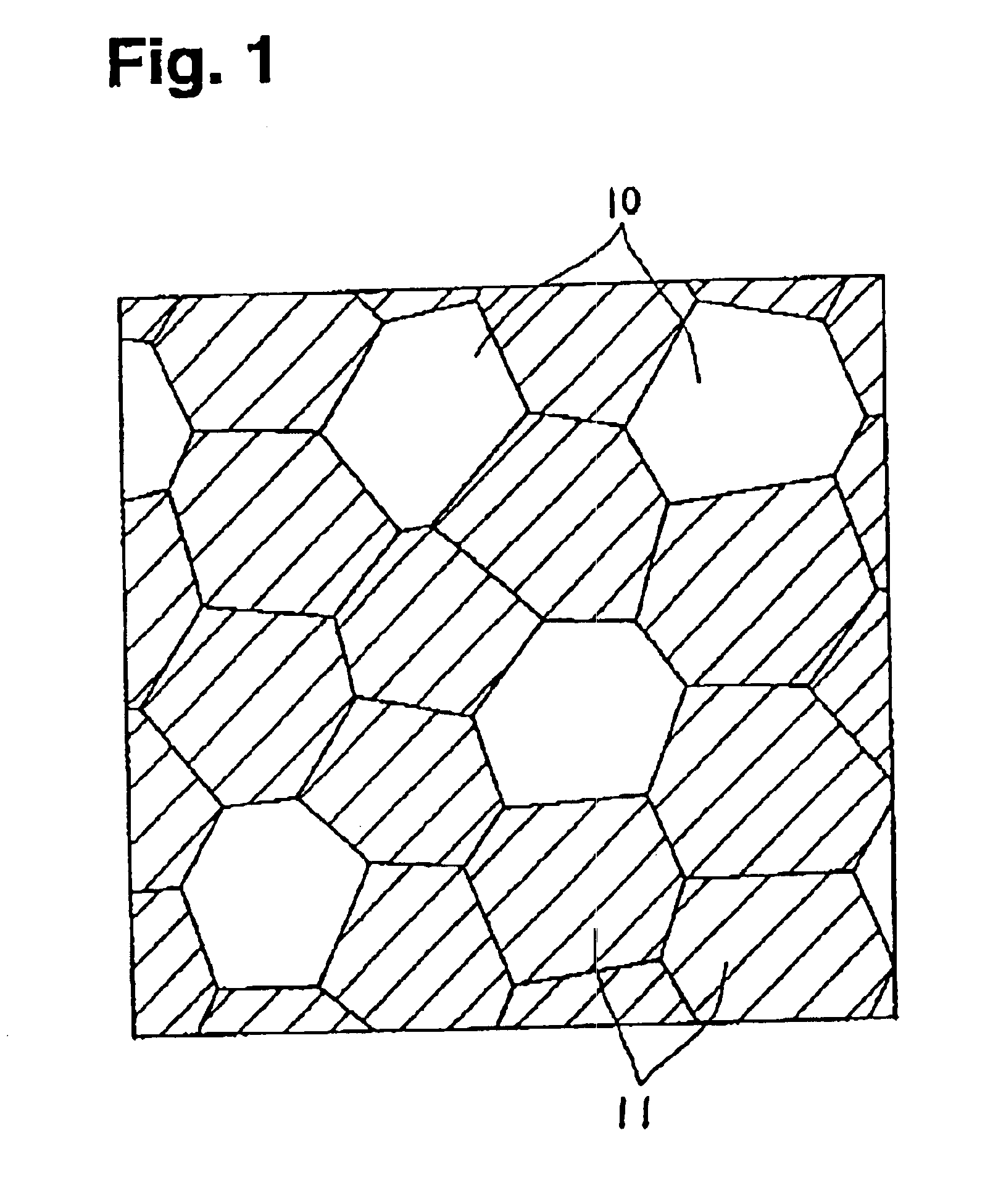
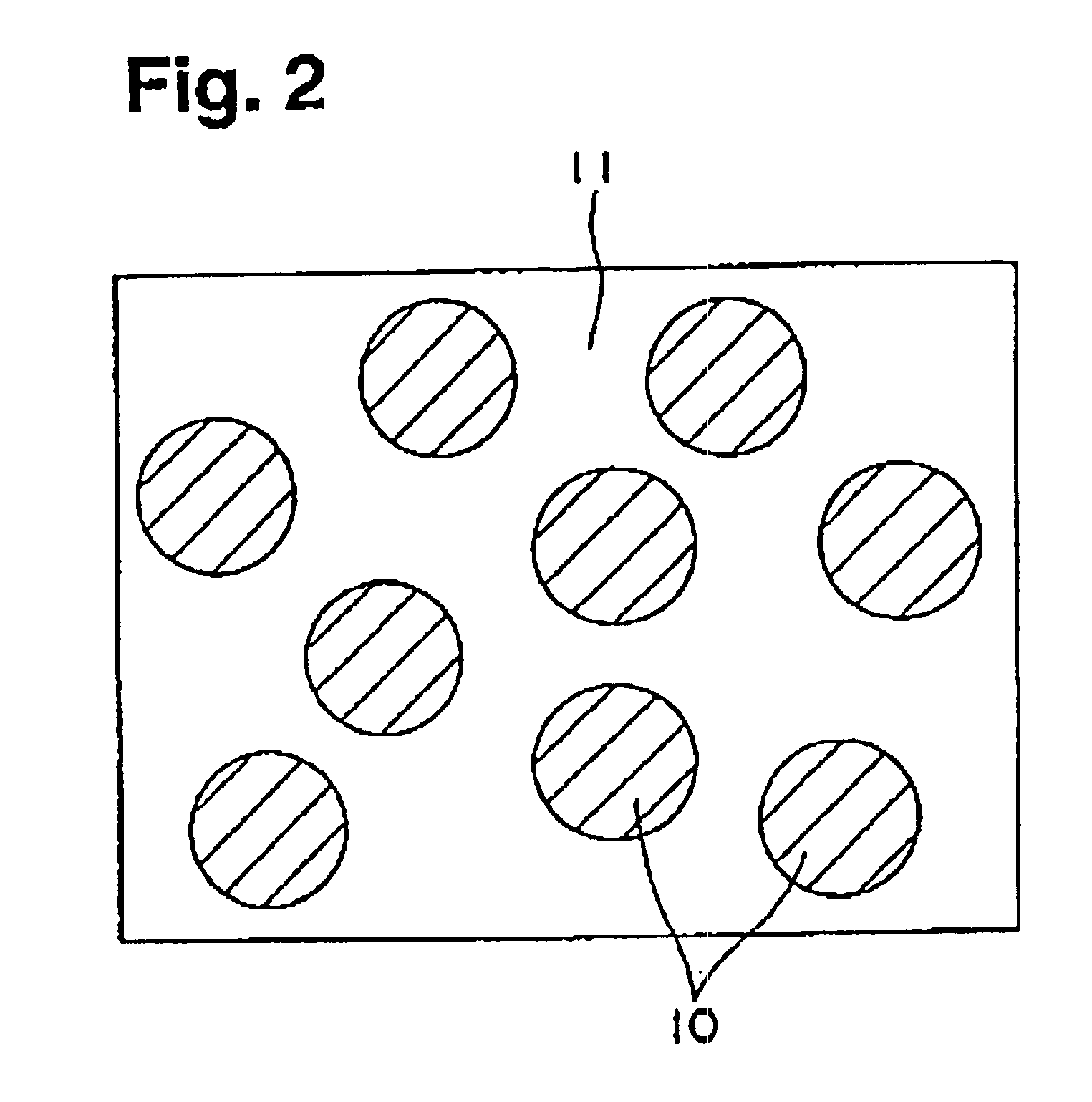
Magnetic powders with alloy compositions Nd8.7Fe77.2-wCo8.5B5.6Siw (that is, various types of magnetic powders in which the content w of Si is changed variously) were obtained by the method described below.

First, each of the materials Nd, Fe, Co, B, and Si was weighed to cast a mother alloy ingot, and a sample of about 15 g was cut out from the ingot.

A quenched ribbon manufacturing apparatus 1 as shown in FIG. 4 and FIG. 5 was prepared, and the sample was placed in a quartz tube 2 having a nozzle (circular orifice) 3 at the bottom. After evacuating the interior of a chamber in which the quenched ribbon manufacturing apparatus 1 is housed, an inert gas (Ar gas and helium gas) was introduced to obtain an atmosphere with desired temperature and pressure.

Then, the ingot sample in the quartz tube 2 was melted by high frequency induction heating, the circumferential velocity and the jetting pressure (difference between the inner pressure of the quartz tube 2 and the pressure of the atmosp...

example 2

Quenched ribbons of which alloy compositions were (Nd1-yPry)8.7FebalCo7.5B5.6Si1.4 (that is, various types of quenched ribbons in which the substitution amount y of Pr is changed variously) were manufactured in the same manner as Example 1, and then the manufactured quenched ribbons were subjected to heat treatment in the argon gas atmosphere at a temperature of 680° C. for 10 minutes. Using the same analyzing method as that used in Example 1, it has been confirmed that the structure of each of the quenched ribbons constitutes a nanocomposite structure.

Next, in the same manner as Example 1, magnetic powders were obtained from the respective quenched ribbons, and then cylindrical (ring-shaped) isotropic bonded magnets having outer diameter of 20 mm, inner diameter of 18 mm and height of 7 mm were manufactured. The content of the magnetic powder in each of the bonded magnets was about 96.8 wt %. Further, the density of each of the bonded magnets was about 6.18 g / cm3.

For these magnetic...

example 3

Quenched ribbons of which alloy compositions were ((Nd0.5Pr0.5)zDY1-z)9.0FebalCo7.7B5.7Si18 (that is, various types of quenched ribbons in which the substitution amount (1-z) of Dy is changed variously) were manufactured in the same manner as Example 1, and then the manufactured quenched ribbons were subjected to heat treatment in the argon gas atmosphere at a temperature of 680° C. for 12 minutes. Using the same analyzing method as that used in Example 1, it has been confirmed that the structure of each of the quenched ribbons constitutes a nanocomposite structure.

Next, in the same manner as Example 1, magnetic powders were obtained from the respective quenched ribbons, and then cylindrical (ring-shaped) isotropic bonded magnets having outer diameter of 20 mm, inner diameter of 18 mm and height of 7 mm were manufactured. The content of the magnetic powder in each of the bonded magnets was about 96.8 wt %. Further, the density of each of the bonded magnets was about 6.20 g / cm3.

For t...


PUM

PropertyMeasurementUnit
grain sizeaaaaaaaaaa
grain diameteraaaaaaaaaa
grain diameter sizeaaaaaaaaaa

Abstract

Disclosed herein is magnetic powder which can provide a magnet having a high magnetic flux density and excellent magnetizability and reliability especially excellent heat resistance property (heat stability). The magnetic powder is composed of an alloy composition represented by Rx(Fe1-yCoy)100-x-z-wBzSiw (where R is at least one kind of rare-earth element, x is 8.1-9.4 at %, y is 0-0.30, z is 4.6-6.8 at %, and w is 0.2-3.0 at %), the magnetic powder being constituted from a composite structure having a soft magnetic phase and a hard magnetic phase, wherein the magnetic powder has characteristics in which, when the magnetic powder is formed into an isotropic bonded magnet by mixing with a binding resin and then molding it, the irreversible susceptibility (χirr which is measured by using an intersection of a demagnetization curve in the J-H diagram representing the magnetic characteristics at the room temperature and a straight line which passes the origin in the J-H diagram and has a gradient ×J/H of −3.8×10⁻⁶ H/m as a starting point is less than 5.0×10⁻⁷ H/m, and the intrinsic coercive force (HCJ) of the magnet at the room temperature is in the range of 406-717 kA/m.

Description

BACKGROUND OF THE INVENTION1. Field of the InventionThe present invention relates to magnetic powder and an isotropic bonded magnet produced using the magnetic powder.2. Description of the Prior ArtFor reduction in size of motors, it is desirable that a magnet has a high magnetic flux density (with the actual permeance) when it is used in the motor. Factors for determining the magnetic flux density of a bonded magnet include magnetic performance (that is, magnetization) of the magnetic powder and the content (that is, compositional ratio) of the magnetic powder in the bonded magnet. Accordingly, when the magnetic performance (magnetization) of the magnetic powder itself is not sufficiently high, a desired magnetic flux density cannot be obtained unless the content of the magnetic powder in the bonded magnet is raised to an extremely high level.At present, most of practically used high performance rare-earth bonded magnets use the isotropic bonded magnets which are made using MQP-B p...

Claims


Application Information

Patent Timeline
Patent Type & Authority Patents(United States)
IPC IPC(8): H01F1/057H01F1/032H01F1/20
CPCB82Y25/00H01F1/0579Y10S977/777Y10S977/775Y10S977/838H01F1/20
Inventor ARAI, AKIRAKATO, HIROSHI
Owner SEIKO EPSON CORP
Why Eureka
Try Eureka