Magnetic film forming method, magnetic pattern forming method and magnetic recording medium manufacturing method

a magnetic film and manufacturing method technology, applied in the field of magnetic film forming method, magnetic pattern forming method and method of manufacturing magnetic recording medium, can solve the problems of easy overwriting of magnetic recording information, track width, and apt interference of adjacent tracks, so as to reduce the roughness of the surface, increase the coercive force of the portion, and reduce the effect of the coercive for

Inactive Publication Date: 2005-09-08
TDK CORPARATION
View PDF5 Cites 0 Cited by
  • Summary
  • Abstract
  • Description
  • Claims
  • Application Information

AI Technical Summary

Benefits of technology

[0021] As described above, according to the method of forming a magnetic film, the method of forming a magnetic pattern and the method of manufacturing a magnetic recording medium in accordance with the invention, it is possible to increase the coercive force of the portion into which only the boron ion is implanted, and furthermore, to reduce the coercive force of the portion into which at least one ion selected from Cr, Al, Nb and Mo and the boron ion are implanted. By implanting the boron ion into the whole surface of the thin film, moreover, it is possible to reduce the surface roughness of the whole surface of the magnetic film obtained after the heat treatment. As a result, it is possible to form the magnetic film having different coercive forces between the portion into which only the boron ion is implanted and the portion into which at least one ion selected from Cr, Al, Nb and Mo and the boron ion are implanted. Therefore, it is possible to form a desirable magnetic pattern substantially having no surface concavo-convex portion by implanting at least one ion selected from Cr, Al, Nb and Mo into a predetermined portion by using a mask, for example.
[0022] By forming, as a track pattern taking the shape of a concentric circle, the portion into which only the boron ion is implanted on a disk-shaped non-magnetic substrate, particularly, it is possible to manufacture a magnetic recording medium such as a discrete track medium having a predetermined magnetic pattern to be the portion into which only the boron ion is implanted without forming a conventional trench. The magnetic recording medium thus manufactured substantially has no surface concavo-convex portion and a manufacturing cost can also be reduced.

Problems solved by technology

However, there is a problem in that adjacent tracks are apt to interfere with each other if the track width is reduced.
More specifically, the reduction in the track width causes a problem in that magnetic recording information is easily overwritten over the adjacent track in recording and a problem in that a cross talk is apt to be generated by a leaking magnetic field from the adjacent track in reproduction.
Both of these problems cause a reduction in the S / N ratio of a reproducing signal and a deterioration in an error rate.
In this method, however, it is hard to implement the stable flying of a magnetic head over the magnetic recording medium because a physical trench is present between the tracks.
On the other hand, although it is possible to stabilize the flying characteristics of the magnetic head over the magnetic recording medium by carrying out a flattening processing after filling the trench between the tracks with a non-magnetic substance, there is a problem in that a manufacturing process is complicated and a manufacturing cost is thus increased.

Method used


Image

  • Magnetic film forming method, magnetic pattern forming method and magnetic recording medium manufacturing method
  • Magnetic film forming method, magnetic pattern forming method and magnetic recording medium manufacturing method
  • Magnetic film forming method, magnetic pattern forming method and magnetic recording medium manufacturing method

Examples


example 1

(Example 1)

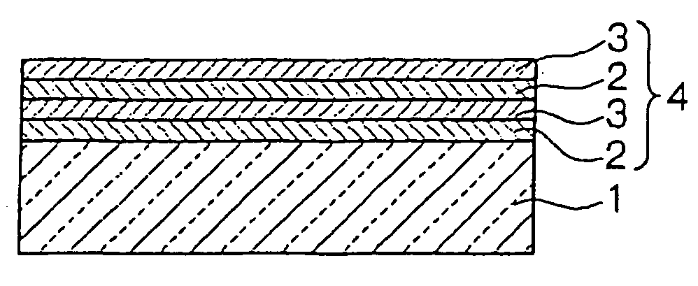
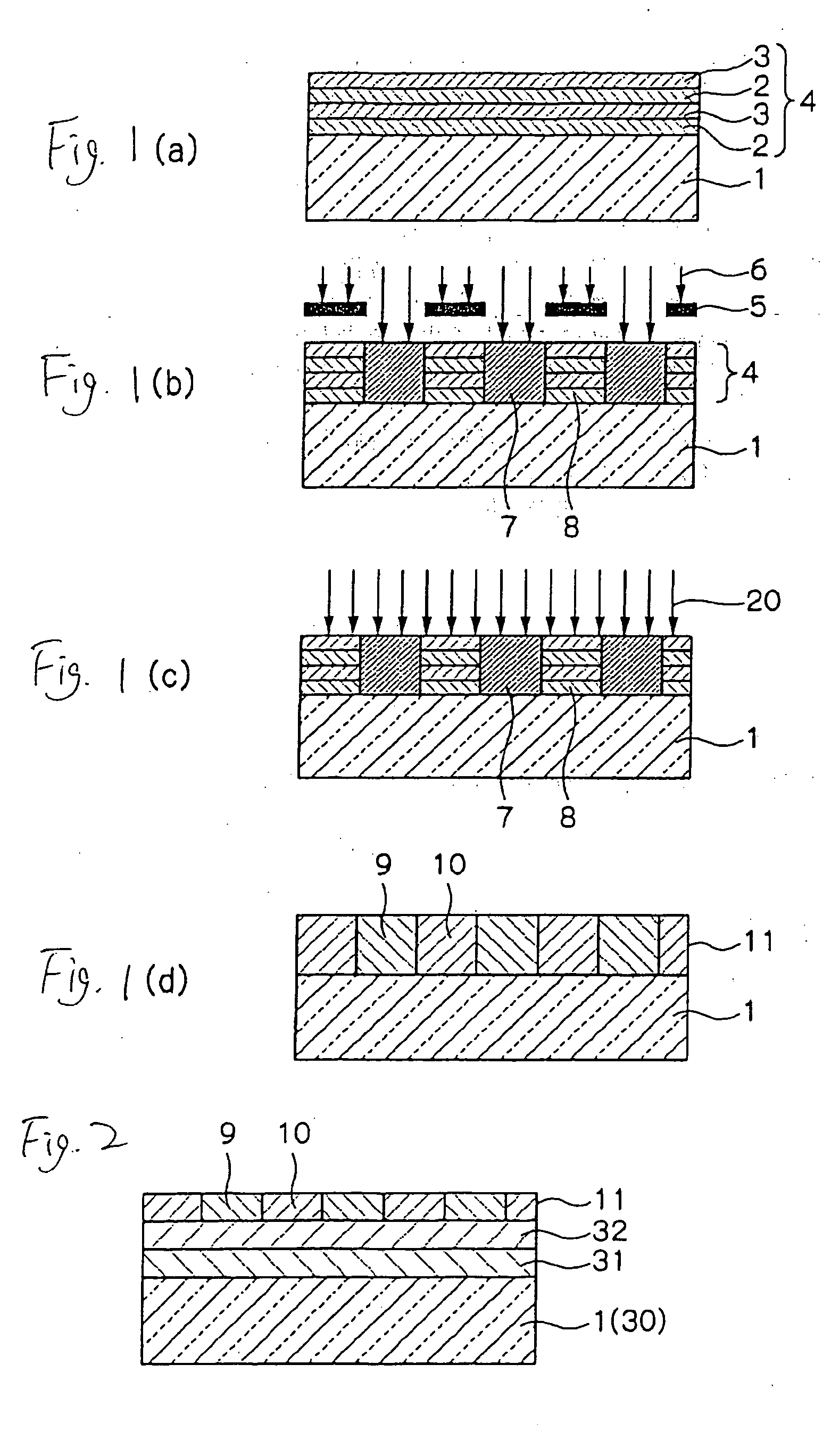
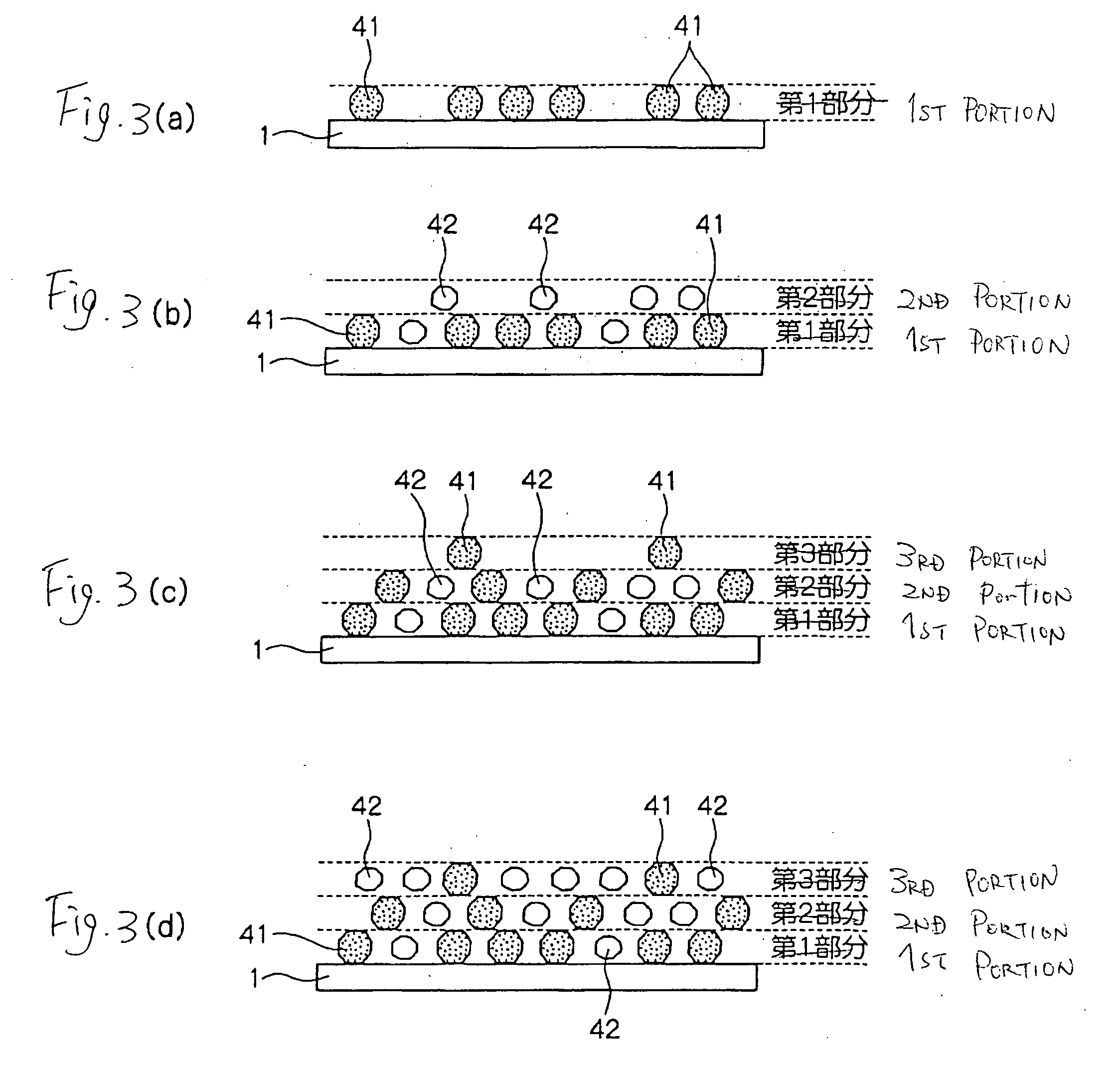
[0074] By using a glass substrate having a thickness of 0.635 mm as the non-magnetic substrate 30, NiFeNb was formed by sputtering so as to be the underlayer film 31 in a thickness of 150 nm, and furthermore, MgO was formed thereon by the sputtering so as to be the intermediate film 32 in a thickness of 3 nm. The Pt atom 41 corresponding to 75% of a necessary amount for forming a Pt single atomic layer was deposited, by the sputtering, on the intermediate film 32 thus formed, and subsequently, the Fe atom 42 corresponding to 75% of a necessary amount for forming an Fe single atomic layer was deposited by the sputtering. Then, the deposition of the Pt atom 41 and that of the Fe atom 42 were alternately repeated, and the depositions were alternately carried out until the number of repetitions is 63. Thus, a thin film was formed. The thin film thus obtained was a compositionally modulated film having a ratio of the Pt atom 41 to the Fe atom 42 of 3:1, 1:1 and 1:3 as one cycl...

example 2

(Example 2)

[0082] Two types of films (samples 7 and 8) were fabricated in the same manner as in the example 1 except that an Al ion was implanted into a film which has not been heat treated in place of the Cr ion according to the example 1. In the samples 7 and 8, the Al ion was implanted into the thin film in the amounts of implantation of 5 atomic % and 10 atomic % at an implanting voltage of 9 keV Referring to the magnetic characteristic of the film thus fabricated, a coercive force Hc in an in-plane direction was measured by means of a vibrating sample magnetometer (VSM) in the same manner as in the example 1. A result is shown in Table 3.

TABLE 3Amount of implantationCoercive forceof Al (atomic %)(Oe)Sample 106200Sample 752681Sample 8103178

[0083] As is apparent from the result of the Table 3, both of the samples 7 and 8 have small coercive forces. Thus, it was found that Al has an effect of suppressing a change to a CuAuI type ordered structure in the same manner as Cr.

example 3

(Example 3)

[0084] Four types of films (samples 9 to 12) were fabricated in the same manner as in the example 1 except that an Nb ion was implanted into a film which has not been heat treated in place of the Cr ion according to the example 1. In the samples 9 to 12, the Nb ion was implanted into the thin film in the amounts of implantation of 2.5 to 20 atomic % at an implanting voltage of 35 keV. Referring to the magnetic characteristic of the film thus fabricated, a coercive force Hc in an in-plane direction was measured by means of a vibrating sample magnetometer (VSM) in the same manner as in the example 1. A result is shown in Table 4. In case of the sample 1, the Nb ion is not implanted.

TABLE 4Amount ofimplantation of NbCoercive force(atomic %)(Oe)Sample 106200Sample 92.52358Sample 1051319Sample 1110927Sample 1220317

[0085] As is apparent from the result of the Table 4, all of the samples 9 to 12 have small coercive forces. Thus, it was found that Nb has an effect of suppressin...


PUM

PropertyMeasurementUnit
thicknessaaaaaaaaaa
thicknessaaaaaaaaaa
thicknessaaaaaaaaaa

Abstract

At least one ion 6 selected from Cr, Al, Nb and Mo is locally implanted into a thin film 4 containing, as main components, at least one of Fe and Co and at least one of Pd and Pt and a boron ion 20 is then implanted into a whole surface of the thin film subjected to the implantation, and a heat treatment is thereafter carried out, and a portion 7 into which at least one ion 6 selected from Cr, Al, Nb and Mo and the boron ion 20 are implanted becomes a portion 9 having a small coercive force and a portion 8 into which only the boron ion 20 is implanted becomes a portion 10 having a large coercive force.

Description

BACKGROUND OF THE INVENTION [0001] The present invention relates to a method of forming a magnetic film, a method of forming a magnetic pattern and a method of manufacturing a magnetic recording medium, and more particularly to a method of forming a magnetic film which can process a magnetic film including a recording portion and a non-recording portion in accordance with a recording pattern. [0002] The performance of a hard disk drive (HDD) has remarkably been enhanced continuously with the development of a computer as a mass storage device capable of carrying out the high-speed access and transfer of data. In particular, an areal density has been enhanced at an annualized rate of 60% to 100% for these 10 years and a further enhancement in the recording density has been required. [0003] In order to enhance the recording density of the hard disk drive (HDD), it is necessary to reduce a track width or a recording bit length. However, there is a problem in that adjacent tracks are apt...

Claims


Application Information

Patent Timeline
Patent Type & Authority Applications(United States)
IPC IPC(8): G11B5/65C23C14/00G11B5/673G11B5/82G11B5/84H01F10/16H01F41/34
CPCB82Y10/00C23C14/48C23C14/5806C23C14/5833H01F10/3236G11B5/855H01F10/123H01F41/34G11B5/82
Inventor AOYAMA, TSUTOMUISHIO, SHUNJIITO, HIROTAKA
Owner TDK CORPARATION
Why Eureka
Try Eureka