
Magnetic recording medium

a magnetic recording and recording drive technology, applied in the direction of magnets, instruments, other domestic objects, etc., can solve the problems of large coercive force, difficult to perfectly isolate the crystal grain of the ferromagnetic film, noise reduction and increase of noise, etc., to achieve noise reduction and high coercive force

Inactive Publication Date: 2004-09-14
FUJITSU LTD
View PDF22 Cites 1 Cited by
  • Summary
  • Abstract
  • Description
  • Claims
  • Application Information

AI Technical Summary

Benefits of technology

A first object of the present invention is to provide a method for manufacturing a magnetic recording medium, which is capable of reducing noise and achieving high coercive force and is fit for a magnetoresistance head.
Therefore, since the silicon containing the magnetic material is not formed, reduction of the magnetic material may be prevented so that the magnetic recording medium having large coercive force and high recording density can be achieved. In addition, since the granular magnetic layer and the diffusion preventing layer excepting the magnetic fine grains are formed by the same substance, difference in thermal stress does not occur in the granular magnetic layer and the diffusion preventing layer. Thus, a stable layer structure can be obtained without the possibility of film exfoliation. A silicon oxide film, for example, can be listed as the nonmagnetic layer. There are iron, cobalt and nickel, for example, as the magnetic grain. Further, an adhesion between a silicon dioxide layer and a silicon substrate is extremely superior and there is no risk of a separation therebetween.

Problems solved by technology

When recording density of the conventional magnetic recording medium is increased, a S / N ratio is degraded to cause reduction of a reproducing output and increase of noise.
In particular, the problem is to achieve noise reduction in the magnetic recording medium since reading sensitivity has been extremely improved by practical use of the magnetoresistance head.
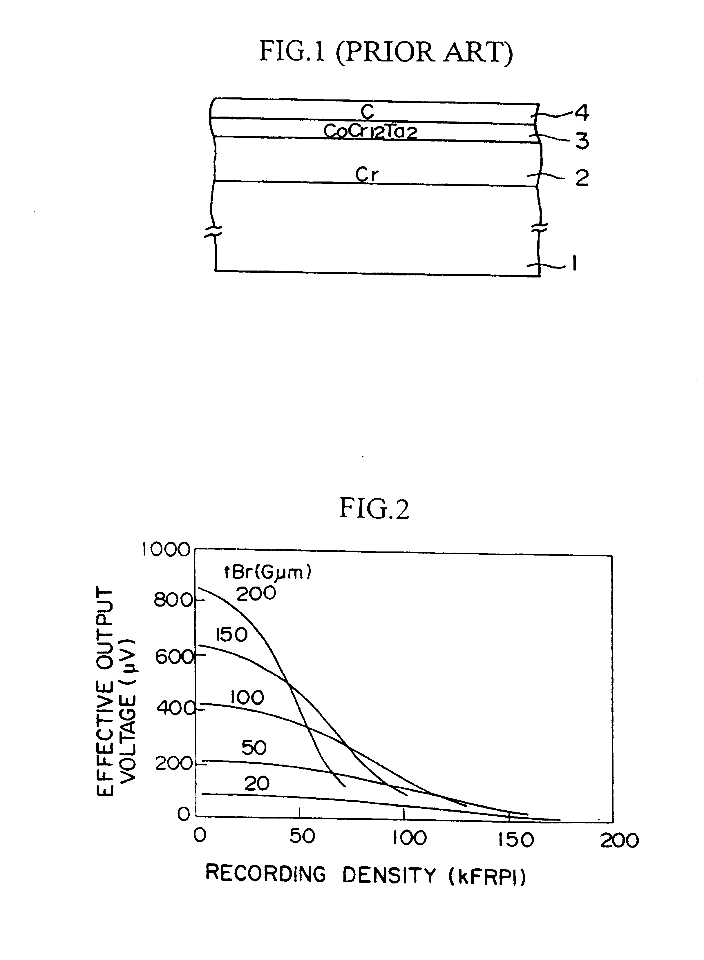
However, since a cobalt system alloy constituting the recording layer 3 is inherently a solid solution, it is difficult to isolate crystal grain of the ferromagnetic film perfectly even if segregation is accelerated by adjusting composition and manufacturing conditions.
However, even under these conditions, noise reduction and large coercive force have not been achieved since crystal grains in the magnetic recording layer are small and further partially continuous with each other in such circumstances.
As a result, it has been found that the thinned CoCr.sub.12 Ta.sub.2 is not fit for the magnetic recording layer used for high recording signal frequency.
As has been stated above, regarding a granular magnetic film (Fe-SiO.sub.2) in which magnetic fine grains are dispersed into the SiO.sub.2 film, the following problem is caused in addition to the problem of the magnetic characteristic due to crystal property of the magnetic recording film.
Thus, there are caused some problems that flatness of the surface of the layer is damaged, the layer is magnetized, or the like.
It is evident that such substrate is not adequate for heating process at a high temperature.
In this case, a thickness of the substrate must also be formed less than 0.3 mm, but it is the problem to use the NiP plated substrate in the respect of mechanical strength.
Especially, in the magnetic recording medium in which a low t.cndot.Br value (where t is a thickness of the magnetic layer, and Br is a magnitude of residual magnetization) is required to be used together with the MR head, it causes a serious problem that the magnetic grain is wasted to form silicon compounds since an amount of the magnetic grain in the magnetic film is absolutely small.
On the other hand, when the magnetic recording medium is formed of a plurality of different material layers and thereafter it is heated, there may be a risk of causing a separation of the layers due to difference between coefficients of thermal expansion of the layers.

Method used


Image

  • Magnetic recording medium
  • Magnetic recording medium
  • Magnetic recording medium

Examples


first embodiment

(1) Explanation of a method for manufacturing a magnetic recording medium according to the present invention:

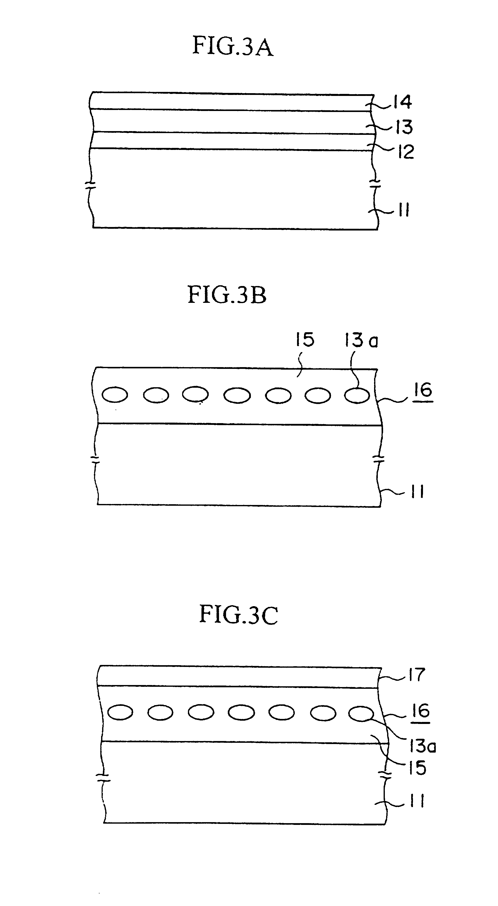
FIGS. 3A to 3C are sectional views showing a manufacturing method of the magnetic recording medium according to the first embodiment of the present invention.

First, as shown in FIG. 3A, a silver (Ag) film (nonmagnetic film) 12 having a film thickness of 5 nm is formed by sputtering on a silicon substrate (nonmagnetic substrate) 11 having a diameter of 2.5 inch, for example, under the conditions that argon pressure is 5 mTorr, a substrate temperature is 20.degree. C., a DC power is 0.2 kW, and a DC bias voltage is not applied.

Then, a cobalt (Co) film (ferromagnetic film) 13 of 7 nm in film thickness is formed on the silver film 12 by sputtering under the conditions that argon pressure is 5 mTorr, a substrate temperature is 20.degree. C., a DC power is 0.2 kW, and a DC bias voltage is not applied.

Subsequently, a silver (Ag) film 14 having a film thickness of 5 nm is formed on t...

second embodiment

(2) Explanation of a method for manufacturing a magnetic recording medium according to the present invention:

FIG. 5 is a sectional view showing a magnetic recording medium manufactured by a manufacturing method according to a second embodiment of the present invention. The second embodiment differs from the first embodiment in that a carbon film is used in place of the silver films between which the cobalt film is put. Also, since a carbon film 18 is utilized on the uppermost portion of the recording layer 19, the protection layer is shared with the carbon film 18 on the recording layer 19.

Referring to FIG. 5, the second embodiment of the present invention will be explained hereinafter.

First, a carbon film (nonmagnetic film) having a film thickness of 5 nm is formed by sputtering on a silicon substrate (nonmagnetic substrate) 11 under the conditions that argon pressure is 10 mTorr, a substrate temperature is 20.degree. C., an AC power having a frequency of 13.56 MHz is 0.2 kW, and a...

third embodiment

The third embodiment is different from the first and second embodiments in the respect that a Co.sub.90 Cr.sub.10 film may be used in place of the cobalt film as the ferromagnetic film sandwiched with the nonmagnetic films.

In comparison with the Co film, the crystal structures of crystal grains of the ferromagnetic film are readily formed as the hcp structures in the Co.sub.90 Cr.sub.10 film, because of existence of Cr therein. Thus, the Co.sub.90 Cr.sub.10 film has a feature that high coercive force can easily be obtained.

A film forming method is the same as that used for the Co film, which has been explained in the first and second embodiments. As a result, the recording layer 21 in which the crystal grains 13 of Co.sub.90 Cr.sub.10 are dispersed into the silver film 20 and mutual crystal grains 13c are perfectly isolated can be formed on the silicon substrate (nonmagnetic substrate) 11.

In this case, as shown in Table I above, assuming that noise power in the conventional example ...


PUM

PropertyMeasurementUnit
average grain diameteraaaaaaaaaa
temperatureaaaaaaaaaa
thicknessaaaaaaaaaa

Abstract

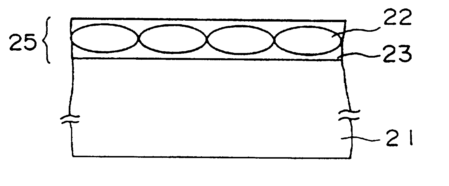
The present invention relates to a magnetic recording medium for use in an external memory device of an information processing apparatus etc., and an object thereof is to reduce noise, achieve high coercive force, and use the substance as a magnetic recording medium for detecting signals in a magnetoresistance head. In the magnetic recording medium comprising the magnetic recording layer 25 including ferromagnetic grains 22 and a nonmagnetic substance 23, the improvement in structure comprises that the ferromagnetic grains 22 are formed to have respectively an average grain diameter of 50 nm or less and not to be overlapped in the film thickness direction and to be isolated in the direction along a layer surface, and that a product of residual magnetization and a film thickness of the magnetic recording layer 25 is less than or equal to 150 Gauss.cndot..mu.m.

Description

BACKGROUND OF THE INVENTION1. Field of the InventionThe present invention relates to a magnetic recording drive, a magnetic recording medium and a method for manufacturing the same and, more particularly, to a magnetic recording drive for use in an external memory device of an information processing apparatus, etc., a magnetic recording medium used therein and a method for manufacturing the same.2. Description of the Prior ArtIn the magnetic recording drive, improvement of the recording density has been demanded more and more with an increase of an amount of information in proportion. When recording density of the conventional magnetic recording medium is increased, a S / N ratio is degraded to cause reduction of a reproducing output and increase of noise. Therefore, the magnetic recording medium enabling a large reproducing output and low noise has been demanded.In particular, the problem is to achieve noise reduction in the magnetic recording medium since reading sensitivity has bee...

Claims


Application Information

Patent Timeline
Patent Type & Authority Patents(United States)
IPC IPC(8): B32B15/04G11B5/64H01F1/00G11B5/66G11B5/70G11B5/714G11B5/855
CPCG11B5/65G11B5/714G11B5/855Y10T428/12465Y10S428/90Y10T428/12118Y10T428/12014Y10T428/115Y10T428/12861Y10T428/31678
Inventor KAITSU, ISATAKEOKAMOTO, IWAOSHINOHARA, MASAYOSHI
Owner FUJITSU LTD
Learn More