Ear canal device retention means

a technology of ear canal and means, which is applied in the direction of earpiece/earphone attachments, electrical transducers, electrical apparatus, etc., can solve the problem that the present solution is not very handy, and achieve the effect of improving the holding for

Active Publication Date: 2007-08-09
OTICON
View PDF9 Cites 33 Cited by
  • Summary
  • Abstract
  • Description
  • Claims
  • Application Information

AI Technical Summary

Benefits of technology

[0009] In an embodiment the strip near the knob and / or the opening is angled with respect to the length direction of the canal device such that the strip will be angled outwardly from the ear canal once the canal device and strip are arranged within the ear canal. Such an outwardly angled strip will give a better holding force and will especially ensure a force towards the ear canal.
[0010] In an embodiment the strip has an oval cross section. When the strip is made from a resilient material, and the oval cross section will provide a uniform force against the inside of the concha and thereby the device will also be comfortable to wear.

Problems solved by technology

However the presented solution is not very handy when it comes to choosing between a device having the retaining means and one without.

Method used


Image

  • Ear canal device retention means
  • Ear canal device retention means
  • Ear canal device retention means

Examples


Embodiment Construction

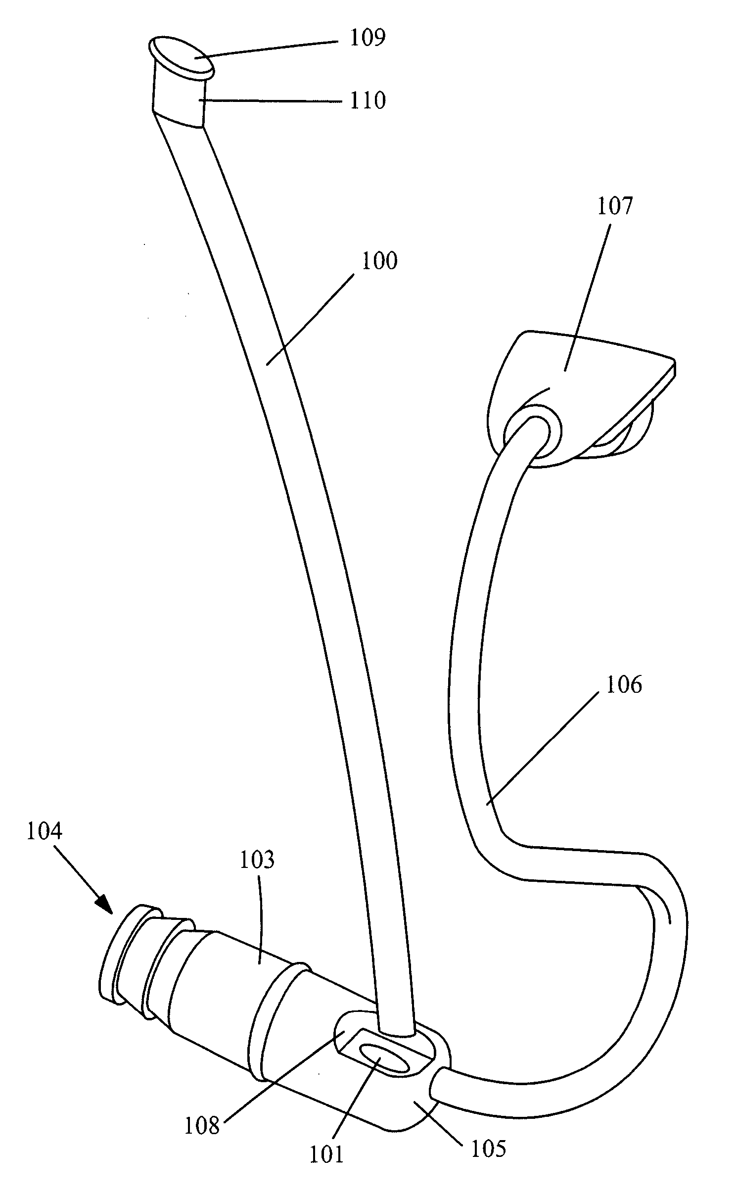
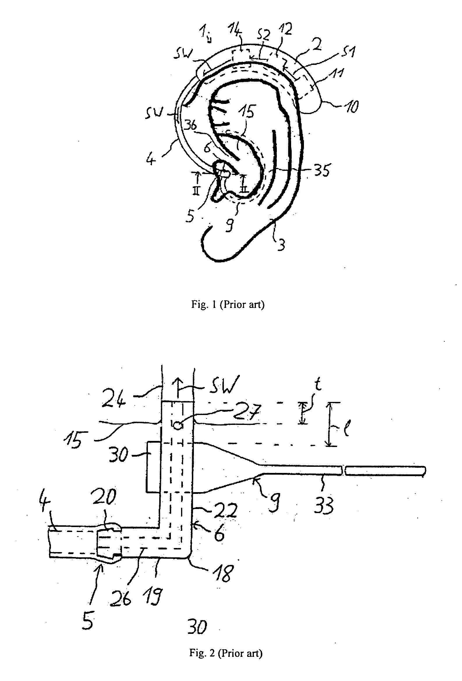
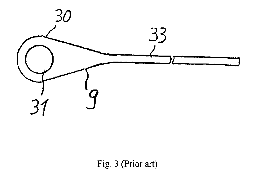
[0017] A prior art solution is disclosed in FIGS. 1-3. This solution is known from DE 20 2004 016 540A1 by Bruckhoff. According to the solution a strip like element 33 (best seen in FIG. 2) is fastened to the ear canal device and caused to lie flat against the lover and back-facing part of the concha, whereby the resilience of the strip 33 exerts a force on the ear canal device, which aids to keep the device in place, also during vigorous movement of the head. As seen in FIGS. 2 and 3 the strip 33 has a wider portion 30 at one end thereof with a hole 31 passing through the wider portion. The ear canal device in this case is a tube 22 and as seen in FIG. 2 the tube is caused to pass through the hole 31 and in this fashion the strip is fastened to the ear canal device. The problem in relation to this solution is that the ear canal device has to be taken apart and detached from a behind the ear part, before the tube 22 can be drawn through the hole 31. This is a rather cumbersome task,...


PUM


Abstract

The invention regards an ear canal device and a retainer strip, whereby the ear canal device has a distal part for extending into the ear canal and facing the tympanic membrane and a proximal part extending towards the ear canal opening, wherein the proximal part of the ear canal device comprises an opening extending transversely through the ear canal device, and where a retaining strip is arranged with a first end thereof arranged to be fastened in the opening and a second end arranged to lie resiliently against the inside of the concha for exerting a retaining force on the ear canal device.

Description

AREA OF THE INVENTION [0001] The invention regards a device for retaining a none-custom unit within the ear canal. None-custom units comprise among others receiver units and tube positioning units, which are to be retained at a predetermined point of insertion within the ear canal in order to deliver a sound signal to the tympanic membrane. Also attenuation devices which are placed in the ear and protects the ear against overly laud sounds and which are used by musicians and others may benefit from the invention. BACKGROUND OF THE INVENTION [0002] Since the ear canal has a tendency to narrow down from entry towards the ear drum, a device attached to the unit placed in the ear, capable of applying an inward force towards the ear drum is desired. Knowing the fact that ear canals differs from person to person, the problem may not be so pronounced for all users, which makes it desirable that this device is detachable. [0003] In a prior art patent application DE 20 2004 016 540A1 by Bruc...

Claims


Application Information

Patent Timeline
Patent Type & Authority Applications(United States)
IPC IPC(8): H04R25/00
CPCH04R1/105H04R1/1058H04R25/656H04R2225/025H04R2460/09H04R25/556H04R25/607
Inventor WURFEL, CLAUS
Owner OTICON
Why Eureka
Try Eureka