Turbomachine rotor wheel

a technology of rotor wheels and turbomachines, which is applied in the direction of liquid fuel engines, marine propulsion, and vessel construction, etc., can solve the problems of deteriorating the blades, and reducing the performance of the turbomachine, so as to achieve the effect of simple, effective and inexpensiv

Active Publication Date: 2007-08-09
SN DETUDE & DE CONSTR DE MOTEURS DAVIATION S N E C M A
View PDF10 Cites 5 Cited by
  • Summary
  • Abstract
  • Description
  • Claims
  • Application Information

AI Technical Summary

Benefits of technology

[0009]A particular object of the invention is to provide a solution to this problem that is simple, inexpensive, and effective.

Problems solved by technology

In operation, the gasket expands radially outwards under the effect of centrifugal force and comes into contact with the blade platforms so as to damp blade vibration and / or to prevent air from passing between the platforms and the outer peripheral surface of the disk, since that would reduce the performance of the turbomachine.
When the turbomachine is at rest, and on starting, the blades of the wheel can tilt to a greater or lesser extent relative to their operating position, and their ends might rub against the outer casing, thereby deteriorating the blades and reducing the performance of the turbomachine.

Method used


Image

  • Turbomachine rotor wheel
  • Turbomachine rotor wheel
  • Turbomachine rotor wheel

Examples


Embodiment Construction

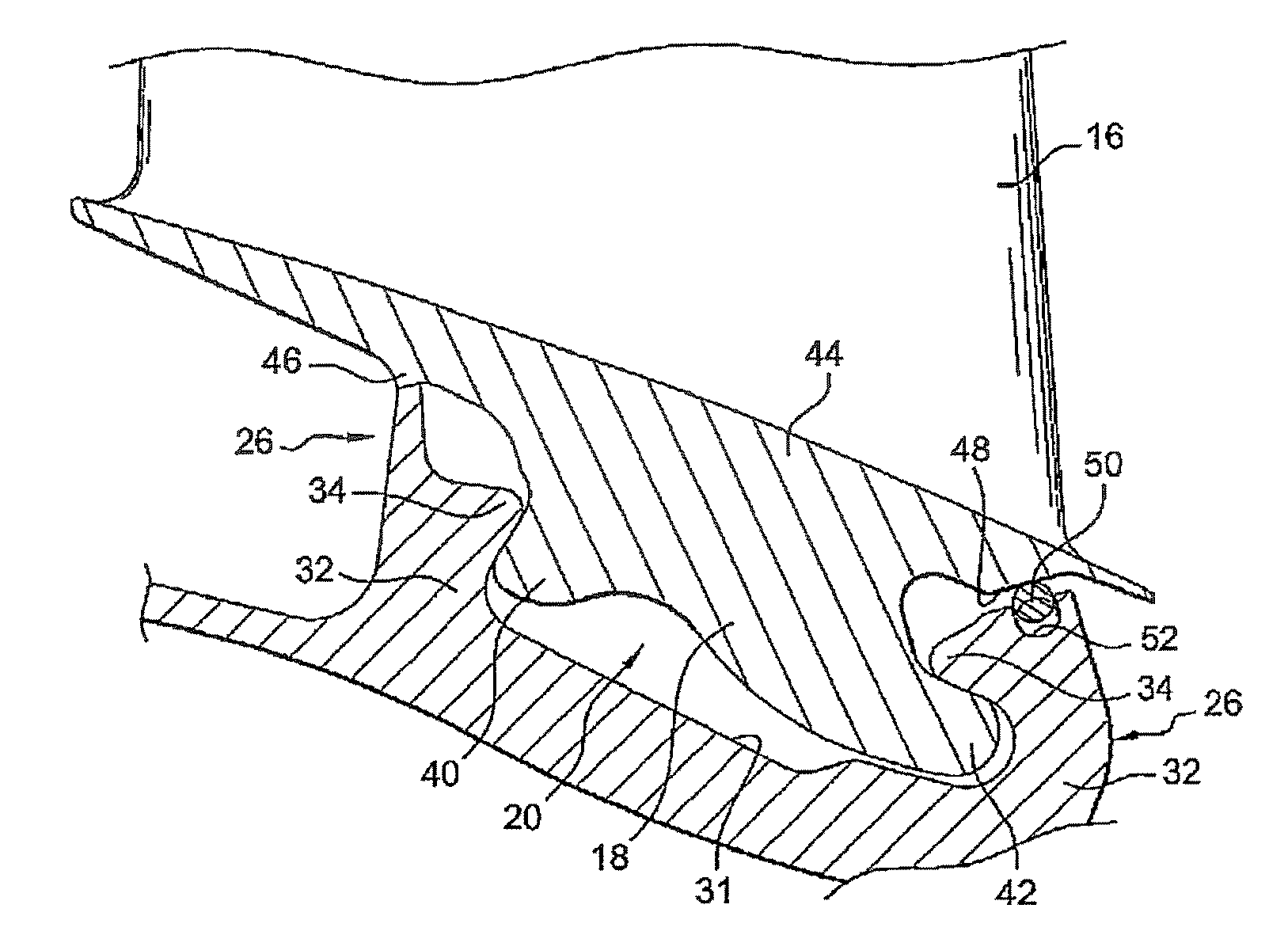
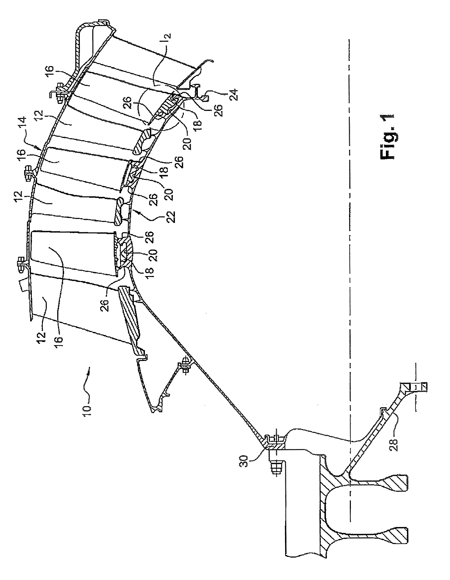
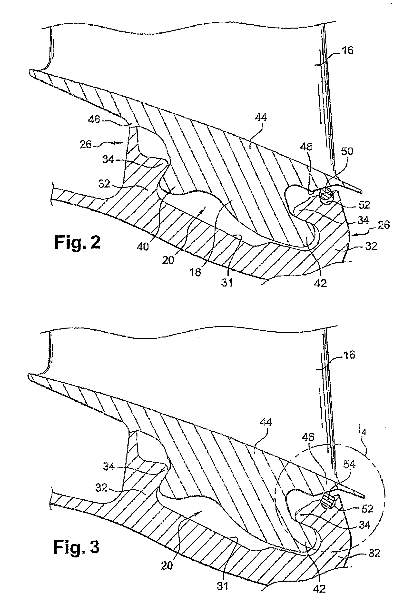
[0028]The low pressure compressor 10 of FIG. 1 has three compression stages, each of these stages having a stationary annular row of stator vanes 12 having their radially outer ends carried by an outer annular casing 14, and an annular row of moving blades 16, arranged downstream from the annular row of stator vanes 12, and having their roots 18 mounted in an annular recess 20 in the outer peripheral surface of a disk 24 of a rotor wheel.

[0029]In the example shown, the disk 24 comprises a circularly symmetrical wall 22 having outer annular ribs 26 with the annular recess 20 for mounting the rows of moving blades 16 being defined between them.

[0030]The disk 24 is connected to a shaft of the turbomachine (not shown) via a drive cone 28 secured to an upstream annular flange 30 of the circularly symmetrical wall 22 of the disk.

[0031]In conventional manner, each recess 20 has a cross-section of the dovetail or similar type and includes a window (not shown) through which the roots 18 of t...


PUM


Abstract

A turbomachine rotor wheel comprises a disk carrying blades having roots engaged and held in an annular recess of the disk, the roots being connected to platforms for co-operating with an annular gasket mounted in an annular groove of the disk, the annular sealing gasket exerting a resilient force on the blade platforms holding the blades in a proper position for operation while the turbomachine is at rest.

Description

[0001]The present invention relates to a rotor wheel, in particular for a turbomachine, the wheel comprising a disk carrying blades having roots that are mounted in an annular recess in an outer peripheral surface of the disk.BACKGROUND OF THE INVENTION[0002]The blade roots are inserted into the recess through a window in a side wall of the recess, and they are then moved circumferentially along the recess so as to be held radially and axially relative to the axis of the wheel by means of co-operating shapes, the recess being of a cross-section that is in the shape of a dovetail or the like, and the blade roots having a shape that is complementary to that of the recess.[0003]The blade roots are connected to the airfoils of the blades by platforms that, when the blades are mounted in the groove and juxtaposed circumferentially, surround the peripheral surface of the disk externally.[0004]Manufacturing and assembly tolerances mean that the blade roots are received with clearance in th...

Claims


Application Information

Patent Timeline
Patent Type & Authority Applications(United States)
IPC IPC(8): F01D5/30
CPCF01D5/00F01D5/3038F05D2250/70F01D25/06F05D2230/64F01D11/006
Inventor LEJARS, CLAUDE ROBERT LOUISTRICONNET, NICOLAS CHRISTIANTHISE, FREDERICK
Owner SN DETUDE & DE CONSTR DE MOTEURS DAVIATION S N E C M A
Why Eureka
Try Eureka