Anti-entrapment and Anti-dead head function

a technology of anti-entrapment and anti-dead head, which is applied in the direction of pump control, non-positive displacement fluid engine, pump control, etc., can solve the problems of damage to the pumping system, risk to damage the pump and/or even injury to the user (i.e., a swimmer) of the aquatic application, and achieve the effect of adapting to consume power

Active Publication Date: 2007-08-09
DANFOSS POWER ELECTRONICS AS +1
View PDF99 Cites 137 Cited by
  • Summary
  • Abstract
  • Description
  • Claims
  • Application Information

AI Technical Summary

Benefits of technology

[0006] In accordance with one aspect, the present invention provides a pumping system for moving water of an aquatic application. The pumping system includes a water pump for moving water in connection with performance of an operation upon the water and a variable speed motor operatively connected to drive the pump. The pumping system further includes means for determining a value indicative of a blockage that inhibits the movement of water through the pumping system and means for determining a performance value of the pumping system. The pumping system further includes means for comparing the performance value to the value indicative of a blockage and means for controlling the motor in response to the comparison between the performance value and the value indicative of a blockage.
[0007] In accordance with another aspect, the present invention provides a pumping system for moving water of an aquatic application. The pumping system includes a water pump for moving water, wherein the water pump is adapted to consume power. The pumping system further includes means for determining a change in power consumption of the water pump and means for determining a blockage that inhibits the movement of water through the pumping system. The determination of a blockage is based at least in part upon the change in power consumption. The pumping system further includes means for controlling operation of the pump to perform an operation upon the water. The means for controlling is configured to alter operation of the pump in response to a determination of a blockage.
[0008] In accordance with another aspect, the present invention provides a pumping system for moving water of an aquatic application. The pumping system includes a water pump for moving water in connection with performance of an operation upon the water and a variable speed motor operatively connected to drive the pump. The pumping system further includes means for determining a threshold value indicative of a blockage that inhibits the movement of water through the pumping system, means for monitoring a performance value of the pumping system, and means for controlling the motor. The means for controlling is configured to alter operation of the motor when the performance value exceeds the threshold value.
[0009] In accordance with yet another aspect, the present invention provides a pumping system for moving water of an aquatic application. The pumping system includes a water pump for moving water in connection with performance of an operation upon the water and a variable speed motor operatively connected to drive the pump. The pumping system further includes means for determining a value indicative of a blockage that inhibits the movement of water through the pumping system and means for determining a performance value of the pumping system during a first time period and a second time period. The pumping system further includes means for determining a difference value based upon the difference between the performance valves of the first and second time periods, means for comparing the difference value and the value indicative of a blockage, and means for controlling the motor in response to the comparison between the difference value and the value indicative of a blockage.
[0010] In accordance with yet another aspect, the present invention provides a pumping system for moving water of a pool or spa used by a pool or spa user. The pumping system includes a water pump for moving water in connection with performance of an operation upon the pool or spa water, an inlet for movement of water from the pool or spa to the pump, and a variable speed motor operatively connected to drive the pump. The system includes means for determining a value that is indicative of a blockage caused by an entrapment of the user at the inlet that inhibits the movement of water through the pumping system and means for determining a performance value of the pumping system. The system includes means for comparing the performance value to the value indicative of a blockage, and means for controlling the motor in response to the comparison between the performance value and the value indicative of a blockage to cause cessation of motor operation.
[0011] In accordance with yet another aspect, a method of controlling a pumping system for moving water of an aquatic application is provided. The pumping system includes a water pump for moving water in connection with performance of an operation upon the water and a variable speed motor operatively connected to drive the pump. The method comprises the steps of determining a value indicative of a blockage that inhibits the movement of water through the pumping system and determining a performance value of the pumping system. The method further comprises the steps of comparing the performance value to the value indicative of a blockage, and controlling the motor in response to the comparison between the performance value and the value indicative of a blockage.

Problems solved by technology

Once the pump is installed, the speed settings typically are not readily changed to accommodate changes in the aquatic application conditions and / or pumping demands.
However, a number of problems can develop in the aquatic application that can pose a risk to damage of the pump and / or even injury to a user (i.e., a swimmer) of the aquatic application.
The obstruction can cause damage to the pumping system, such as by a “water hammer” effect and / or by excessive loading of the pumping system.
Though most pools and spas include suction drain grates, the grates can be loose, missing, and / or damaged over time.
Thus, when a user stands or sits on the loose, missing or damaged drain grate, the suction from the pumping system can hold the user underwater and can cause drowning or other injuries.

Method used


Image

  • Anti-entrapment and Anti-dead head function
  • Anti-entrapment and Anti-dead head function
  • Anti-entrapment and Anti-dead head function

Examples


Embodiment Construction

[0019] Certain terminology is used herein for convenience only and is not to be taken as a limitation on the present invention. Further, in the drawings, the same reference numerals are employed for designating the same elements throughout the figures, and in order to clearly and concisely illustrate the present invention, certain features may be shown in somewhat schematic form.

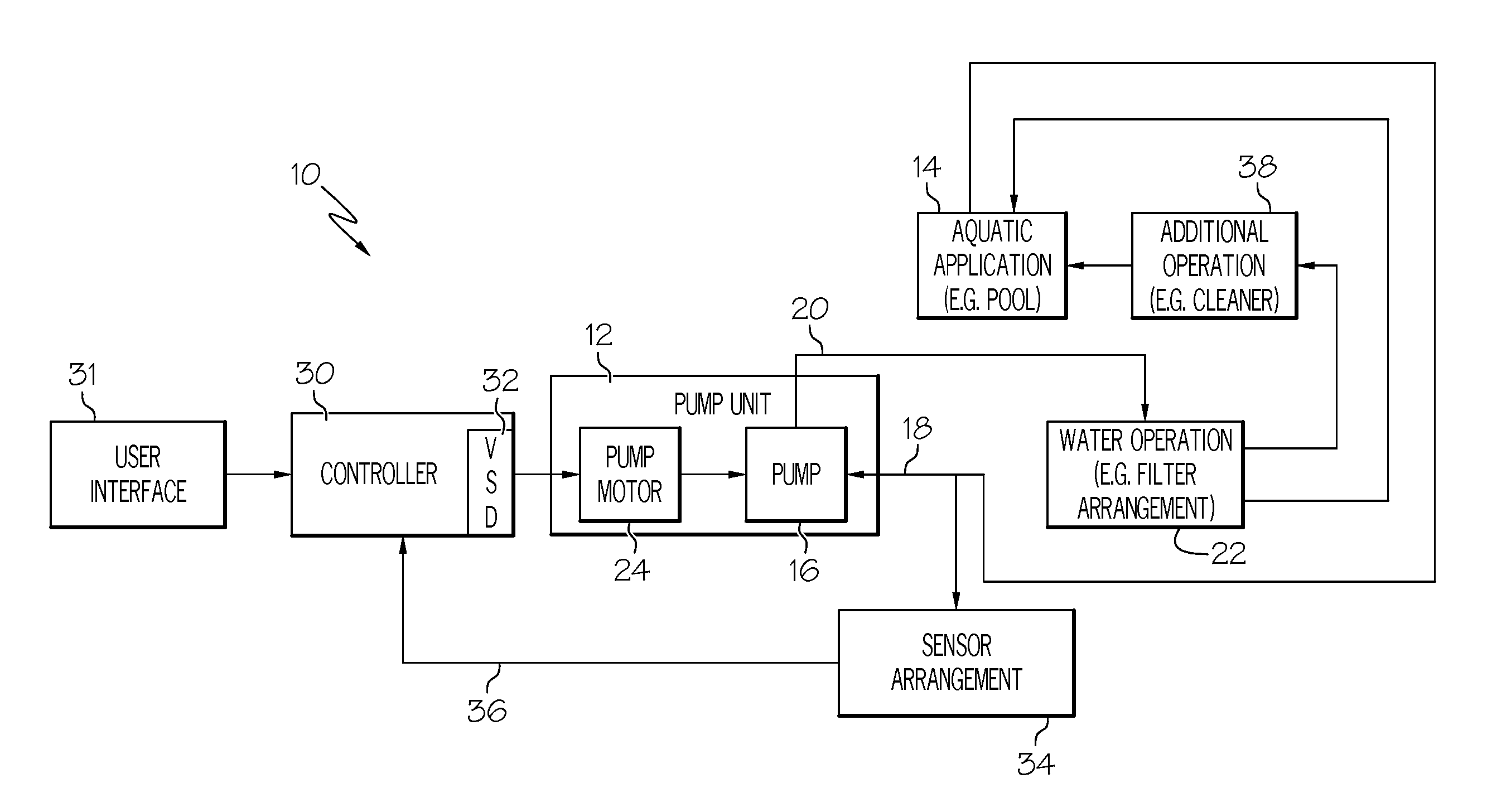
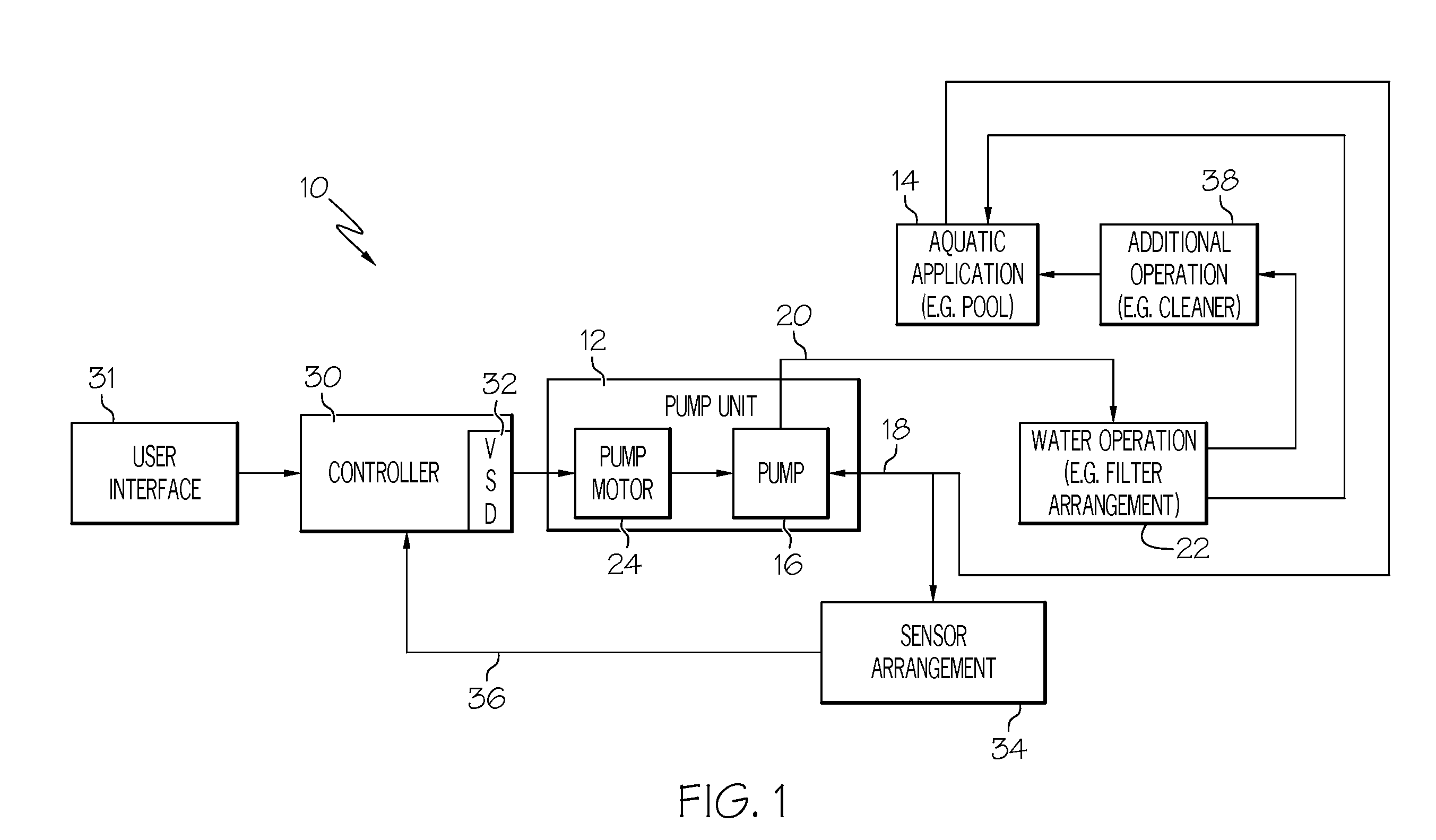
[0020] An example variable-speed pumping system 10 in accordance with one aspect of the present invention is schematically shown in FIG. 1. The pumping system 10 includes a pump unit 12 that is shown as being used with a pool 14. It is to be appreciated that the pump unit 12 includes a pump 16 for moving water through inlet and outlet lines 18 and 20.

[0021] The pool 14 is one example of an aquatic application with which the present invention may be utilized. The phrase “aquatic application” is used generally herein to refer to any reservoir, tank, container or structure, natural or man-made, having a fluid...


PUM


Abstract

A pumping system includes a water pump for moving water. The pumping system includes means for determining a value indicative of a blockage that inhibits the movement of water through the pumping system, and means for determining a performance value of the pumping system. In one example, the pumping system includes means for comparing the performance value to the value indicative of a blockage and means for controlling the pump in response to the comparison. In another example, the system includes means for determining a change in power consumption of the water pump. In another example, the system includes means for determining a threshold value and means for controlling the pump when the performance value exceeds the threshold value. In another example, the system includes means for determining a difference value based upon a plurality of performance valves during a first time period and a second time period. A method of controlling the pumping system is also included.

Description

RELATED APPLICATIONS [0001] This application is a continuation-in-part application of U.S. application Ser. No. 10 / 926,513, filed Aug. 26, 2004, and U.S. application Ser. No. 11 / 286,888, filed Nov. 23, 2005, the entire disclosures of which are hereby incorporated herein by reference.FIELD OF THE INVENTION [0002] The present invention relates generally to control of a pump, and more particularly to control of a variable speed pumping system for a pool, a spa or other aquatic application. BACKGROUND OF THE INVENTION [0003] Conventionally, a pump to be used in an aquatic application such as a pool or a spa is operable at a finite number of predetermined speed settings (e.g., typically high and low settings). Typically these speed settings correspond to the range of pumping demands of the pool or spa at the time of installation. Factors such as the volumetric flow rate of water to be pumped, the total head pressure required to adequately pump the volume of water, and other operational p...

Claims


Application Information

Patent Timeline
Patent Type & Authority Applications(United States)
IPC IPC(8): F04B49/00
CPCF04B49/20F04D15/0077F04D15/0066F04D13/06F04D15/0254F05D2270/335F04D15/0088
Inventor STILES, ROBERT W. JR.BERTHELSEN, LARS HOFFMANNWESTERMANN-RASMUSSEN, PETERKJAER, GERTLUNGEANU, FLORIN
Owner DANFOSS POWER ELECTRONICS AS
Why Eureka
Try Eureka