
Coated material welding with multiple energy beams

Inactive Publication Date: 2003-08-19
EDISON WELDING INSTITUTE INC
View PDF10 Cites 51 Cited by
  • Summary
  • Abstract
  • Description
  • Claims
  • Application Information

AI Technical Summary

Benefits of technology

When a conventional circular or elongated energy beam is used, lap welds in coated materials with zero gap between the surfaces during welding produce high levels of porosity due to 1) vaporization of the coating material that spews out the material to be welded as the coating violently boils off, 2) entrapment of gas / vapor bubbles of the coating in the weld, and 3) humping of the weld at higher weld speeds using an elongated beam. On the other hand, multiple separated energy beams from either multiple sources or single beam division according to the present invention, produce high quality (porosity free) lap welds in coated materials with zero gap. Multiple, separated, energy beams appear to extend the beam keyhole and increase the time and conditions available for vapor / gas to diffuse less violently through the weld.

Problems solved by technology

Unfortunately, the presence of the coating presents a major problem that limits the application of laser welding.
When coated steel is laser welded in a lap-joint configuration, the low boiling point of the coating at the interface of the two sheets results in vaporization of the coating material.
However, industry is continuously looking for methods of laser welding coated steel in a lap-joint configuration with no gap because it is difficult to maintain a controlled gap in production.
Researchers around the world have been attempting to produce high quality laser lap welds with zero gap for at least 15 years with little if any success.
Attempts by the present inventors to use the oblong beam to improve lap weld quality for zinc-coated steel with no gap resulted in non-acceptable welds.
A specified weld defect that occurred with the oblong beam was humping (the periodic accumulation of portions of the base material that project above the surface of the sheet material) which was especially severe at high welding speeds.

Method used


Image

  • Coated material welding with multiple energy beams
  • Coated material welding with multiple energy beams

Examples


Embodiment Construction

The present invention features a no gap (zero gap) method for beam welding of coated materials such as steels, aluminum alloys, and other coated products including materials coated with inorganic and plastic coverings. A number of welding experiments were conducted on zinc-coated steels to assess the feasibility of producing high quality lap welds with zero gap using multiple energy beams. The materials included hot-dipped galvanized, electro-galvanized, and galvannealed steel. These materials were laser welded in a lap-joint configuration with zero gap between two sheets.

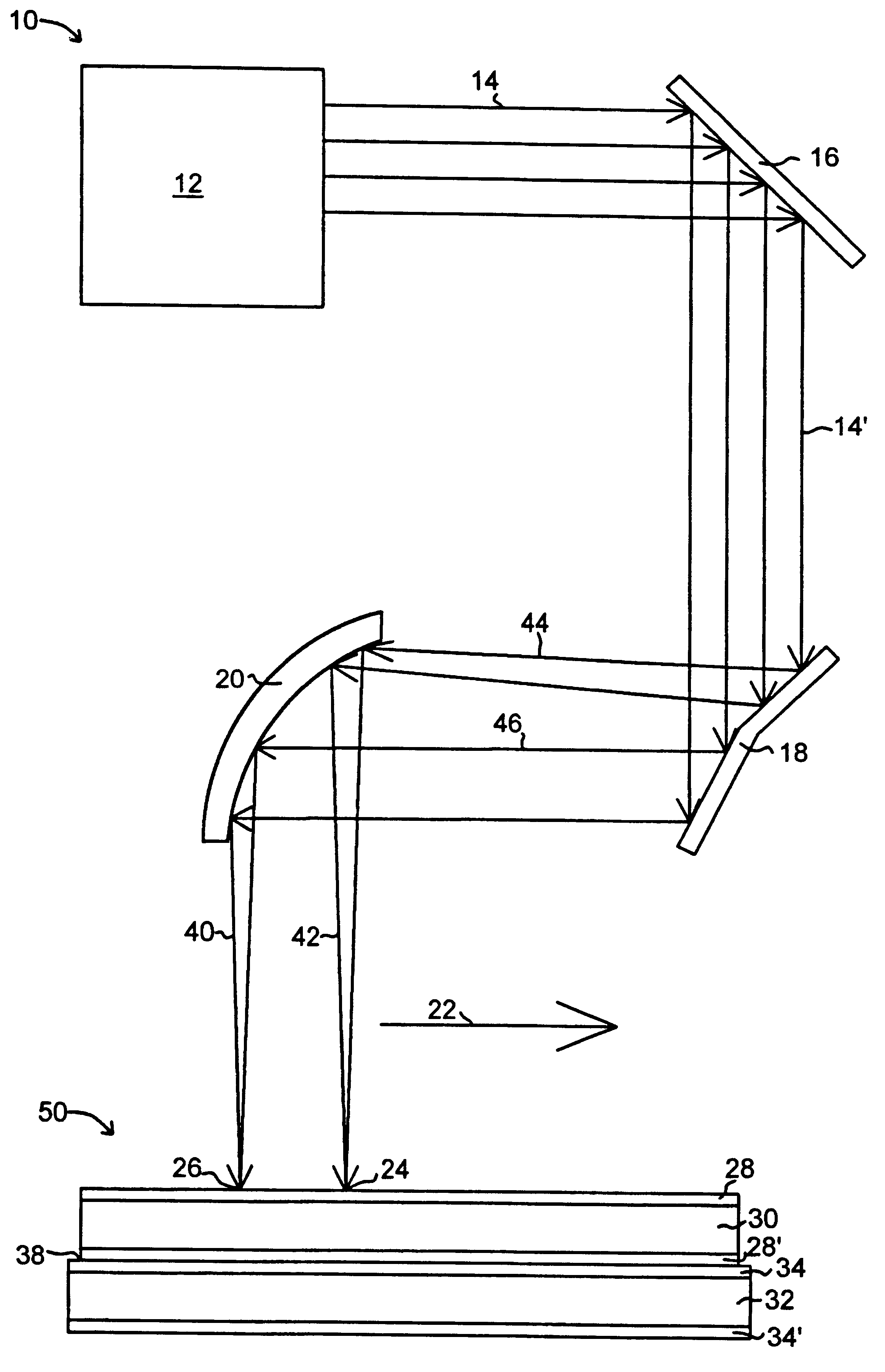
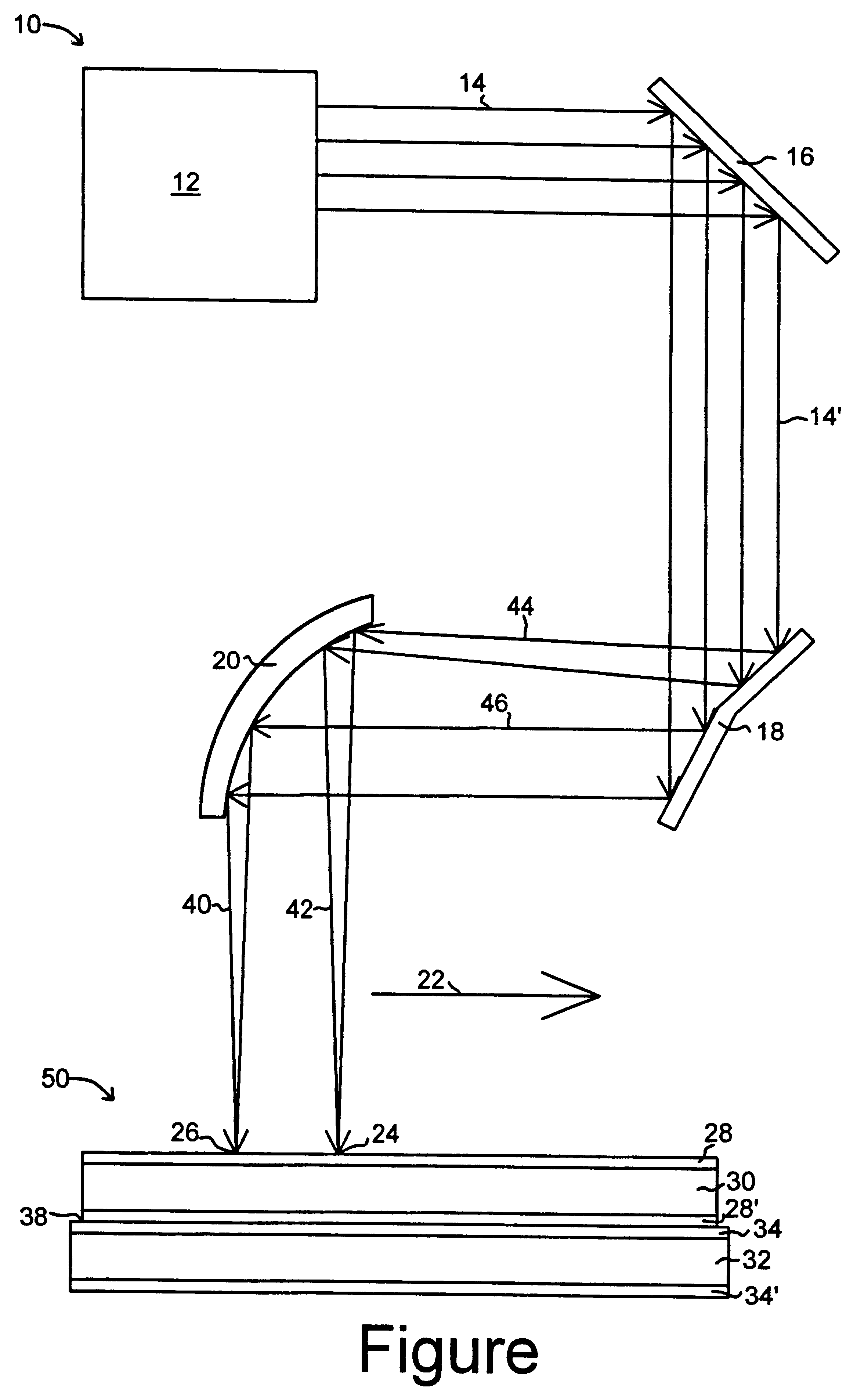
As shown in the Figure, the welding stack 50 is comprised of two layers of material 30 and 32 in a lap-joint configuration with no gap between the interface 38 of the two layers. Each of the layers 30 and 32 is coated with a coating material 28, 2' and 34,34', respectively, on both the upper and lower surfaces of each layer 30 and 32. It is to be realized, however, that only one interface 38 side of one of the laye...


PUM

PropertyMeasurementUnit
Lengthaaaaaaaaaa
Diameteraaaaaaaaaa
Energyaaaaaaaaaa

Abstract

To overcome 1) the high levels of porosity due to coating material vaporization and entrapment into the weld, 2) spewing of molten base metal from the weld leaving holes and pits in the weld, and 3) humping effects when oblong beam configurations are used at higher weld speeds to weld coated materials, the present invention features an energy source (10) with multiple separated energy beams (24, 26) (formed by using multiple separate beam sources or manipulation of a single beam (14) into separated multiple energy beams (44, 46) using wedge mirror (18) and parabolic focusing mirror (20)) that produces high quality (porosity free) lap welds in a weld stack (50) of layered materials (30, 32) coated with coating material (28, 28', 34, 34') with zero gap at interface (38) during the welding process. An energy source (12) with multiple, separated energy beams (24, 26) extends the beam keyhole and increases the time and conditions available for vapor / gas to diffuse less violently through the molten weld pool.

Description

1. Field of the InventionThis invention pertains to the welding of coated materials and more particularly energy beam welding such as laser and electron beam welding of coated materials such as zinc and organic coated steel and other coated materials using an energy source with multiple, separated, energy beams.2. Background of the InventionCoated steels are used to make a variety of components for a number of industries. For example, zinc-coated steels are used for corrosion resistance for automobile bodies. Laser welding offers many advantages over conventional welding processes for joining zinc-coated steels such as one-sided access, less flange material (weight reduction), high welding speed, and improved structural stiffness. Consequently, there is major interest in developing reliable laser welding procedures to join coated steels in a lap-joint configuration. Unfortunately, the presence of the coating presents a major problem that limits the application of laser welding. The ...

Claims


Application Information

Patent Timeline
IPC IPC(8): B23K26/32B23K26/06B23K26/067B23K26/24B23K26/00
CPCB23K26/0608B23K26/067B23K26/246B23K26/3206B23K26/3226B23K26/3293B23K2203/04B23K26/32B23K26/244B23K2101/006B23K2101/34B23K2103/04B23K2103/08B23K2103/10B23K2103/166B23K2103/50
Inventor XIE, JIANDENNEY, PAUL EDWARD
Owner EDISON WELDING INSTITUTE INC
Learn More