
Membrane electrode assembly for fuel cell, method of preparing the same, and fuel cell using the membrane electrode assembly for fuel cell

Inactive Publication Date: 2007-08-09
SAMSUNG SDI CO LTD
View PDF8 Cites 13 Cited by
  • Summary
  • Abstract
  • Description
  • Claims
  • Application Information

AI Technical Summary

Benefits of technology

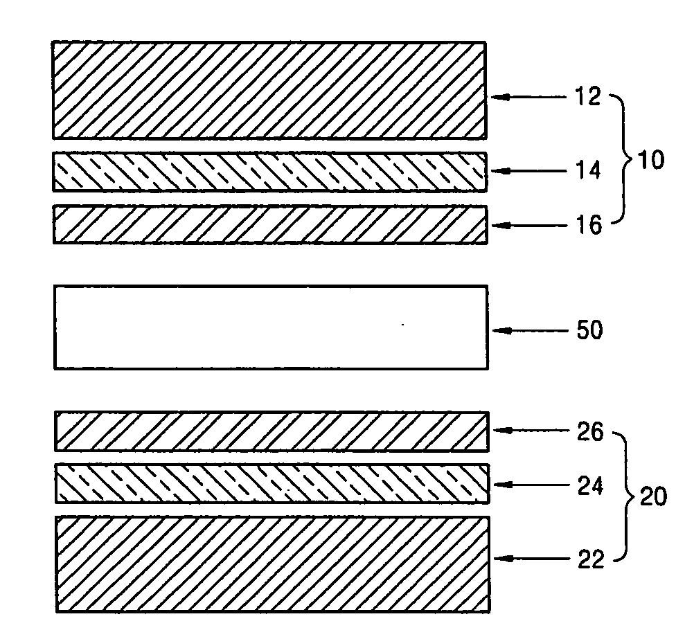
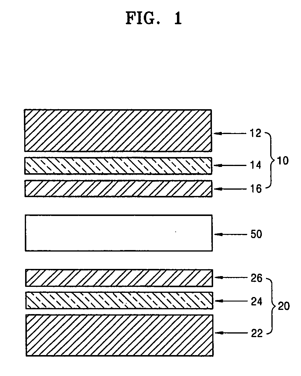
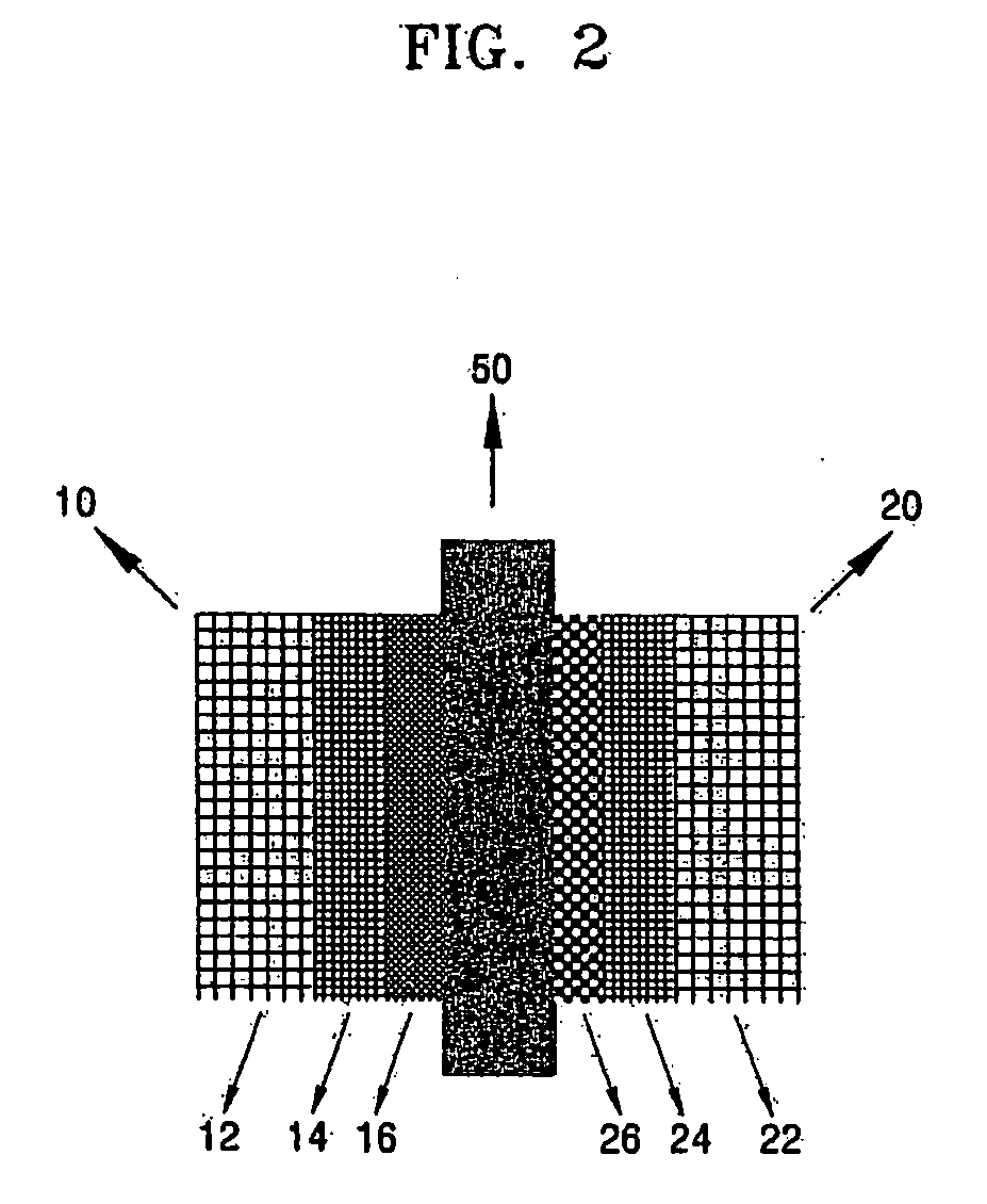
[0012] Aspects of the present invention provide a membrane electrode assembly in which air can be easily supplied to a cathode and water easily flow out of the cathode, thereby obtaining high performance of the membrane electrode assembly; and an anode catalyst layer has relatively small pores, thereby obtaining high durability of an anode and reducing the diffusion speed of methanol in the anode catalyst layer to maintain the initial performance of a battery for a long time, a method of preparing the same, and a fuel cell including the membrane electrode assembly.

Problems solved by technology

However, when the flow of the oxidant in the cathode of a conventional MEA is insufficient, water generated in the cathode is not sufficiently removed, and thus, pores of the support become blocked.
In this case, however, the current collecting properties of a battery decrease in comparison to a battery in which a binder having a water repelling property is not used.
Also, in the case of an anode of a conventional MEA, the anode can be degraded by methanol, and thus, the durability of the anode can decrease over time.
Then, it becomes difficult to obtain the same electrode performance as prior to the deterioration.

Method used


Image

  • Membrane electrode assembly for fuel cell, method of preparing the same, and fuel cell using the membrane electrode assembly for fuel cell
  • Membrane electrode assembly for fuel cell, method of preparing the same, and fuel cell using the membrane electrode assembly for fuel cell
  • Membrane electrode assembly for fuel cell, method of preparing the same, and fuel cell using the membrane electrode assembly for fuel cell

Examples


example 1

[0068] Example 1

[0069] Carbon black powder, polytetrafluoroethylene, and isopropylalcohol were mixed in a weight ratio of 100: 5: 500 in a sonic bath for 2 hours, thereby preparing an anode diffusion layer slurry. The prepared anode diffusion layer slurry was coated onto 400 nm-thick carbon paper (GDL 10 series, SGL carbon group) and sintered at 170° C. for one hour, thereby preparing an anode diffusion layer unit.

[0070] PtRu black, used as an anode catalyst, was mixed with water, NAFION, and isopropylalcohol in a weight ratio of 10: 15: 200 based on 100 parts by weight of the anode catalyst in a sonic bath for two hours, thereby preparing an anode catalyst layer slurry. The prepared anode catalyst layer slurry was coated onto a PET film by screen printing and then dried at 70° C. for 2 hours, thereby preparing an anode unit, which was transferred onto an electrolyte membrane (NAFION 115 membrane produced by Dupont Co.) The anode unit was transferred to the electrolyte membrane by ...


PUM

PropertyMeasurementUnit
Temperatureaaaaaaaaaa
Diameteraaaaaaaaaa
Diameteraaaaaaaaaa

Abstract

A membrane electrode assembly for a fuel cell, a method of preparing the same, and a fuel cell using the membrane electrode assembly for a fuel cell. The membrane electrode assembly includes an anode comprising an anode substrate, an anode diffusion layer, and an anode catalyst layer having pores; a cathode comprising a cathode substrate, a cathode diffusion layer, and a cathode catalyst layer having pores; and an electrolyte membrane interposed between the cathode and the anode, wherein the anode diffusion layer is hydrophilic and the cathode diffusion layer is hydrophobic, and the average diameter of the pores of the anode catalyst layer is smaller than the average diameter of the pores of the cathode catalyst layer. In the membrane electrode assembly, air can be easily supplied to the cathode and water can easily flow out of the cathode, thereby obtaining high performance of the membrane electrode assembly, and the anode catalyst layer has relatively small pores, thereby improving durability of the anode and reducing the diffusion speed of methanol in the anode catalyst layer to maintain the initial performance of a battery for a long time.

Description

CROSS-REFERENCE TO RELATED PATENT APPLICATIONS [0001] This application claims the benefit of Korean Application No. 2006-11833, filed Feb. 7, 2006, in the Korean Intellectual Property Office, the disclosure of which is incorporated herein by reference. BACKGROUND OF THE INVENTION [0002] 1. Field of the Invention [0003] Aspects of the present invention relate to a membrane electrode assembly for a fuel cell, a method of preparing the same, and a fuel cell using the membrane electrode assembly. More particularly, aspects of the present invention relate to a membrane electrode assembly in which air can be easily supplied to a cathode and water can easily flow out of the cathode, thereby obtaining high performance of the membrane electrode assembly; and in which an anode catalyst layer has relatively small pores, thereby obtaining high durability of an anode and reducing the diffusion speed of methanol in the anode catalyst layer to maintain the initial performance of a battery for a lo...

Claims


Application Information

Patent Timeline
IPC IPC(8): H01M4/94H01M4/88
CPCH01M4/8605H01M4/861H01M4/8807H01M4/881H01M4/8814Y02E60/523H01M4/8896H01M8/04261H01M8/04291H01M8/1009H01M8/1011H01M4/8817H01M8/04197Y02E60/50Y02P70/50G01N33/442B29B17/02B29B2017/0275
Inventor KIM, JI-RAELEE, SEUNG-JAEPARK, JUN-YOUNGYOON, HAE-KWONLEE, JOON-HYUNG
Owner SAMSUNG SDI CO LTD
Learn More