Microfluidic device for purifying a biological component using magnetic beads

a microfluidic device and biological component technology, applied in the field of biological component isolation, can solve the problems of complex network of intersecting channels, cost, and diagnostic systems based on microfluidic technology have not reached their potential,

Inactive Publication Date: 2007-08-09
CAPLIPER LIFE SCI INC +1
View PDF4 Cites 239 Cited by
  • Summary
  • Abstract
  • Description
  • Claims
  • Application Information

AI Technical Summary

Problems solved by technology

Microfluidic devices designed to carry out complex analyses will often have complicated networks of intersecting channels.
For the most part, diagnostic systems based on microfluidic technology have failed to reach their potential, so only a few such systems are currently on the market.
Two of the major shortcomings of current microfluidic diagnostic devices relate to cost and to difficulties in sample preparation.
Issues related to cost arise because materials that are inexpensive to process into chips, such as many common polymers, are not necessarily chemically inert or optically transparent enough to be suitable for diagnostic applications.
However, issues of cross-contamination from previously processed samples can arise.
Processing of raw biological samples such as blood or other bodily fluids in microfluidic devices can be problematic.
For example, raw biological samples can clog the narrow channels in a microfluidic device, especially if beads are also present in the channels.
Difficulties can also arise if the component of interest in the sample is present in a low concentration.
Thus, if a large volume of sample needs to be processed to extract an adequate amount of a low concentration sample, the extraction process can be very time consuming.
Quite often genetic materials of interest are present in low concentrations in a raw biological sample, so the extraction of enough genetic material for PCR amplification from the sample within a microfluidic device can be extremely time consuming, sometimes taking several hours.
Although magnetic beads have been used within microfluidic devices to extract a component of interest from a sample, such extraction processes are subject to the previously described problems when the sample is a raw biological sample.
Indeed, the presence of beads within a microfluidic channel further narrows the effective flow cross section of the channel, thus exacerbating the previously described issues arising from clogging and low volumetric flow rates.
Also, the flow of a raw sample through microfluidic channels can be difficult to control, since the fluid properties of the raw sample are generally not known.

Method used


Image

  • Microfluidic device for purifying a biological component using magnetic beads
  • Microfluidic device for purifying a biological component using magnetic beads
  • Microfluidic device for purifying a biological component using magnetic beads

Examples


Embodiment Construction

[0027] As noted previously, embodiments of the present method are directed to extracting a component of interest from a raw biological sample with magnetic beads. Sample preparation processes in accordance with the invention take place in a microfluidic device.

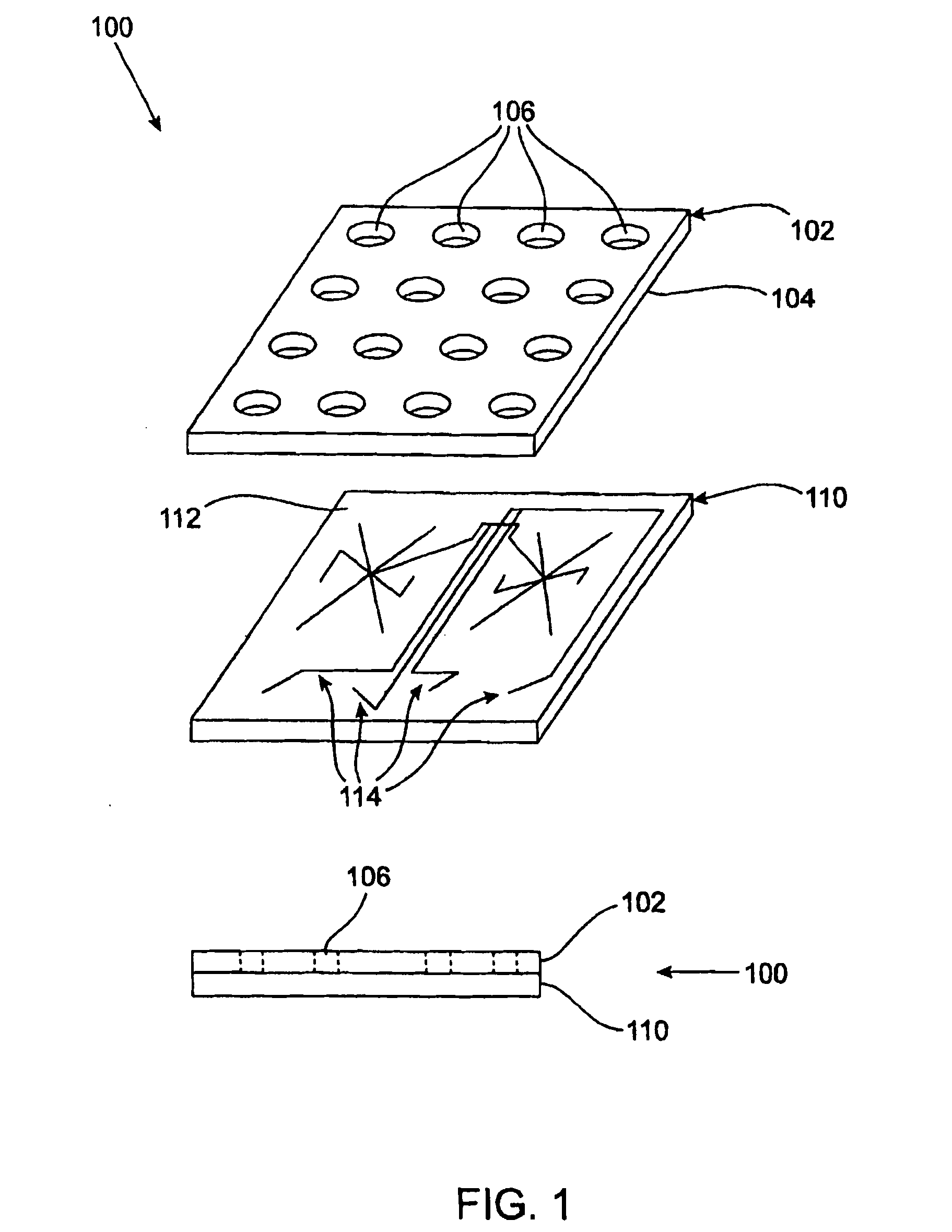
[0028]FIG. 1 is a generic representation of a typical microfluidic device that can be used to carry out methods in accordance with the invention. The top portion of FIG. 1 shows an exploded view of the device 100, which consists of two planar substrates 102,110; and the bottom portion of FIG. 1 shows a side view of the assembled device 100 after the two planar substrates 102,110 have been bonded together. Structures such as channels or chambers are formed within the interior of the assembled microfluidic device 100 by fabricating a pattern of grooves and trenches 114 on a surface 112 of one substrate 110 and bonding a corresponding surface 104 of the other substrate 102 onto the patterned surface 112. When the substrates are ...


PUM

PropertyMeasurementUnit
radiusaaaaaaaaaa
thicknessaaaaaaaaaa
diameteraaaaaaaaaa

Abstract

A method of purifying a biological component found in a biological sample by extracting the biological component from the biological sample. The method is performed using a microfluidic device having at least one well for receiving the biological sample and at least one channel for introducing and removing fluids. A plurality of magnetic beads having a factor with an affinity for the biological component is introduced to the well together with a suitable biological sample. The biological sample is manipulated to release the biological component in proximity to the magnetic beads which are then segregated within the well while removing the biological sample. An elution solution for the biological component is introduced to the well and the elution solution together with the biological component are withdrawn therefrom.

Description

TECHNICAL FIELD [0001] The present invention relates to the isolation of a component of interest from a biological sample. More particularly, embodiments of the present invention are directed toward purifying and thus preparing a component of interest in a biological sample for further manipulation within a microfluidic device. BACKGROUND OF THE INVENTION [0002] Microfluidics refers to a set of technologies involving the flow of fluids through channels having at least one linear interior dimension, such as depth or radius, of less than 1 mm. It is possible to create microscopic equivalents of bench-top laboratory equipment such as beakers, pipettes, incubators, electrophoresis chambers, and analytical instruments within the channels of a microfluidic device. Since it is also possible to combine the functions of several pieces of equipment on a single microfluidic device, a single microfluidic device can perform a complete analysis that would ordinarily require the use of several pie...

Claims


Application Information

Patent Timeline
Patent Type & Authority Applications(United States)
IPC IPC(8): C12Q1/68C12M3/00
CPCB01L3/502761B01L2200/027B01L2200/0668G01N35/0098B01L2400/0415B01L2400/0487G01N1/34B01L2300/0816
Inventor MOLHO, JOSHFOREMAN, PAMELA
Owner CAPLIPER LIFE SCI INC
Why Eureka
Try Eureka