System and method for positioning a laparoscopic device

a laparoscopic device and positioning system technology, applied in the field of system for positioning a laparoscopic device, can solve the problems of difficulty in adjusting the positioning position,

Inactive Publication Date: 2007-08-09
CIVCO MEDICAL INSTR CO
View PDF13 Cites 67 Cited by
  • Summary
  • Abstract
  • Description
  • Claims
  • Application Information

AI Technical Summary

Benefits of technology

[0028] The present invention further relates to a new set of devices and a method that is particularly suited for holding, positioning and repositioning a laparoscopic camera throughout a laparoscopic surgical procedure. The device includes a holder with joints for permitting rotational movement and positioning of a clamping end for securing a laparoscopic instrument. Fixed positioning and manual re-positioning may be quickly accomplished by simply overcoming the modest frictional resistance to movement within the devices without any mechanical adjustments after the initial set up. The joints of the holder may remain free to move at all times. When the holder is static it preferably will not move, and thus, in effect, becomes self locking because of the physical / mechanical relationship of the various system components including the laparoscopic instrument such as an endoscopic camera which is secured in the holder and extending through the skin of the patient. In addition, the multi-modality holder has alternative functionality for holding and positioning other laparoscopic instruments.

Problems solved by technology

Unfortunately, good assistance, or any assistance for that matter, is frequently unavailable, and the surgeon must work solo.
However, these alternatives each have one or more troublesome drawbacks.
The high end robotic arms (such as da Vinci) are expensive, have high maintenance requirements, are time consuming and cumbersome to set up and may have high cost disposable components.
The simpler, voice controlled (AESOP) or palm radio controlled (LAPMAN) robotic arms also require significant maintenance and set up time, move too slowly for many surgeons, and are hard to precisely control.
The mechanical arms and frameworks that are available typically have too many movable parts that require adjustment, require two hands for re-positioning, may have a large footprint near the surgical field, and are very slow to re-position because of the several joints that must be loosened and retightened.
In this device, the clamp that holds the laparoscopic camera at the free end of the flexible arm has limited capabilities; the clamp becomes locked dimensionally with the arm and is not a universal joint.

Method used


Image

  • System and method for positioning a laparoscopic device
  • System and method for positioning a laparoscopic device
  • System and method for positioning a laparoscopic device

Examples


Embodiment Construction

[0051] The instrument holders described herein are particularly useful in minimally invasive surgical procedures using a laparoscope (laparoscopic camera), which is a type of endoscope (endoscopic camera). It should be understood that each of the terms laparoscope, laparoscopic camera, endoscope, and endoscopic camera as individually used with respect to any particular embodiment are not meant to limit that embodiment to a laparoscopic or endoscopic context.

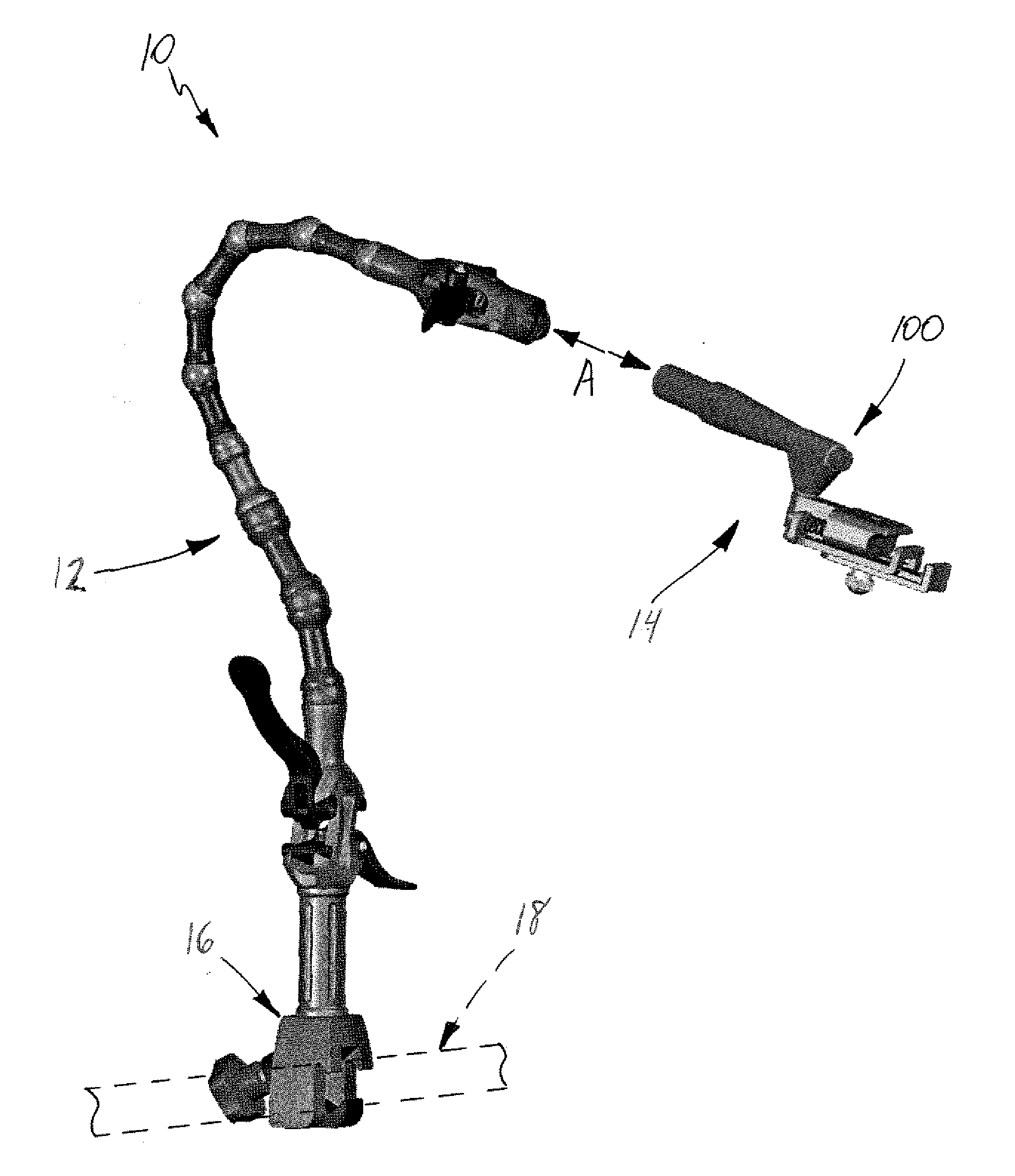
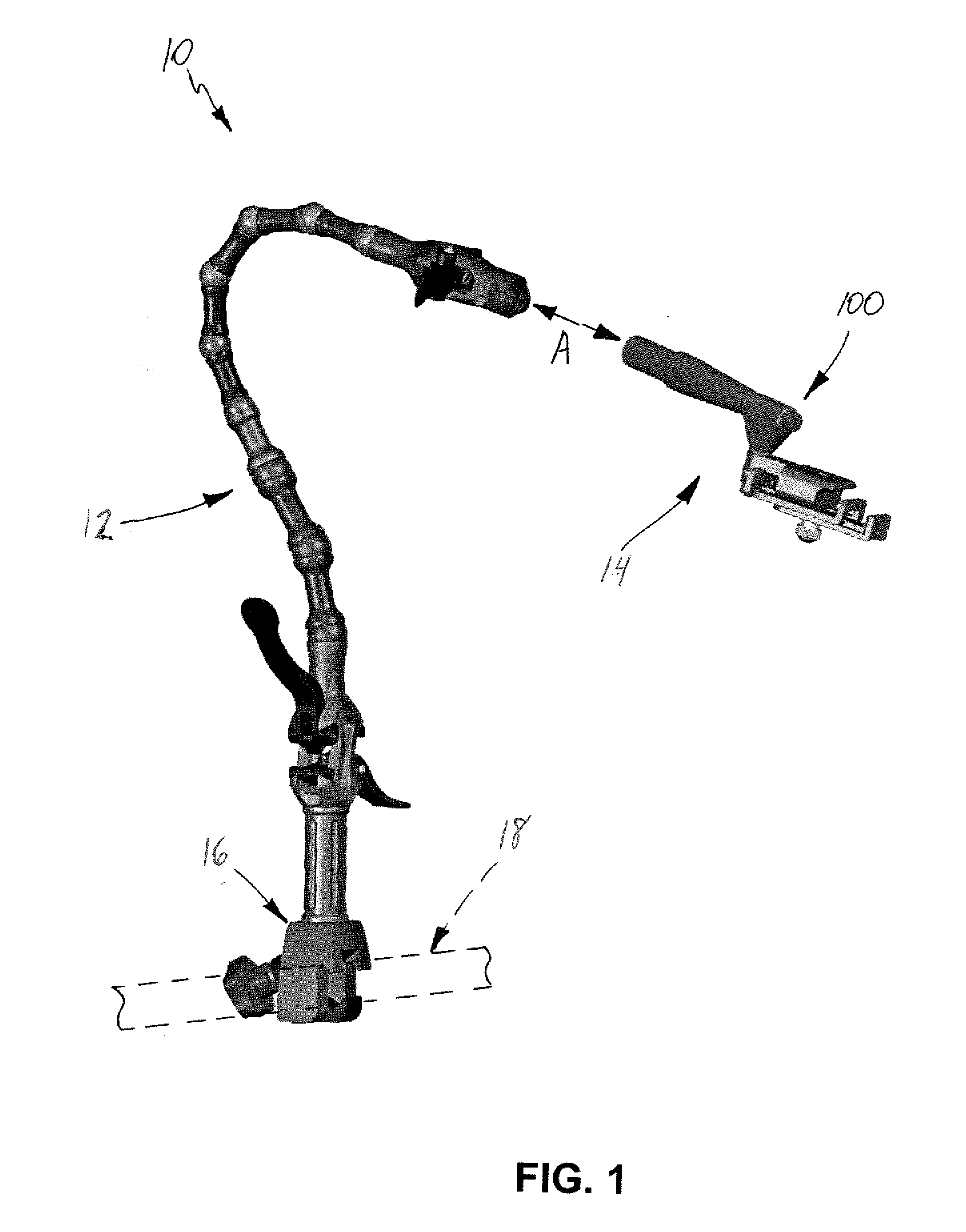
[0052] Referring initially to FIG. 1, an exemplary embodiment of a laparoscopic instrument holder system 10 according to the present invention is shown. Holder system 10 includes a curvilinear articulating arm assembly 12 and a laparoscopic instrument holder 14 coupled to assembly 12 as indicated by arrow A. As will be further described, arm assembly 12 includes a clamp 16 at a first free end thereof for coupling system 10 to a structure such as the rail 18 (shown schematically in phantom) of an operating room table.

[0053] Turn...


PUM


Abstract

A system for positioning a laparoscopic device includes a curvilinear articulating arm and a holder. The holder has at least two rotational regions and a clamping portion for receiving the laparoscopic device, and the holder is coupled to the curvilinear articulating arm. The at least two rotational regions are permitted to articulate. In addition, a method of positioning a laparoscopic device in a skin port of a mammal includes: securing the laparoscopic device to a holder having at least two rotational joints; coupling the holder to a curvilinear articulating arm; disposing the laparoscopic device partially within the skin port; positioning the laparoscopic device by selectively articulating the curvilinear articulating arm and selectively rotating portions of the holder with respect to one another.

Description

CROSS-REFERENCE TO RELATED APPLICATIONS [0001] This application is a continuation-in-part of application Ser. No. 11 / 095,586 filed Apr. 1, 2005 and entitled “Support System for Use When Performing Medical Imaging of a Patient” which claims the benefits of Provisional Application No. 60 / 559,414 filed Apr. 2, 2004, Provisional Application No. 60 / 575,792 filed May 28, 2004, and Provisional Application No. 60 / 614,593 filed Oct. 1, 2004 under 35 U.S.C. § 119(e), and the entire contents of each of these applications are expressly incorporated herein by reference thereto. [0002] In addition, the benefits of Provisional Application No. 60 / 709,098 filed Aug. 18, 2005, Provisional Application No. 60 / 730,853 filed Oct. 28, 2005, Provisional Application No. 60 / 772,863 filed Feb. 14, 2006, and Provisional Application No. 60 / 773,638 filed Feb. 16, 2006, each entitled “System for Positioning a Laparoscopic Device,” as well as Provisional Application No. 60 / 821,692 filed Aug. 7, 2006 and entitled “...

Claims


Application Information

Patent Timeline
Patent Type & Authority Applications(United States)
IPC IPC(8): A61B1/00
CPCA61B17/02A61B19/26A61B2017/00858A61B2019/268A61B2017/00991A61B2019/267A61B2017/00862A61B90/50A61B90/57A61B2090/571
Inventor WILSON, ROGER F.WHITMORE, WILLET F. III
Owner CIVCO MEDICAL INSTR CO
Why Eureka
Try Eureka