Deposition apparatus and method for depositing film

a technology of deposition apparatus and film, which is applied in the direction of chemical vapor deposition coating, metal material coating process, coating, etc., to achieve the effect of preventing clogging of the exhaust line due to a reaction of these gases in the exhaust line, constant flow rate of supplied gas, and improving deposition characteristics

Active Publication Date: 2007-08-16
RENESAS ELECTRONICS CORP
View PDF23 Cites 280 Cited by
  • Summary
  • Abstract
  • Description
  • Claims
  • Application Information

AI Technical Summary

Benefits of technology

[0028]This can provide a supply of the second gas into the reaction chamber when the first gas is adsorbed on the substrate, and therefore the second gas can be continually supplied in reaction chamber. Having this configuration, a constant pressure of the second gas supplied into the reaction chamber can be maintained, thereby maintaining a constant flow rate of the supplied gas. Therefore, an improved deposition characteristics can be presented.
[0029]Further, since simultaneous exhaust of the first gas and the second gas directly to the exhaust line is avoided according to the above-described aspect of the present invention, a clogging of the exhaust line due to a react

Problems solved by technology

Further, the supply of the first gas is stopped when the second gas is excited, and thus a p

Method used


Image

  • Deposition apparatus and method for depositing film
  • Deposition apparatus and method for depositing film
  • Deposition apparatus and method for depositing film

Examples


first embodiment

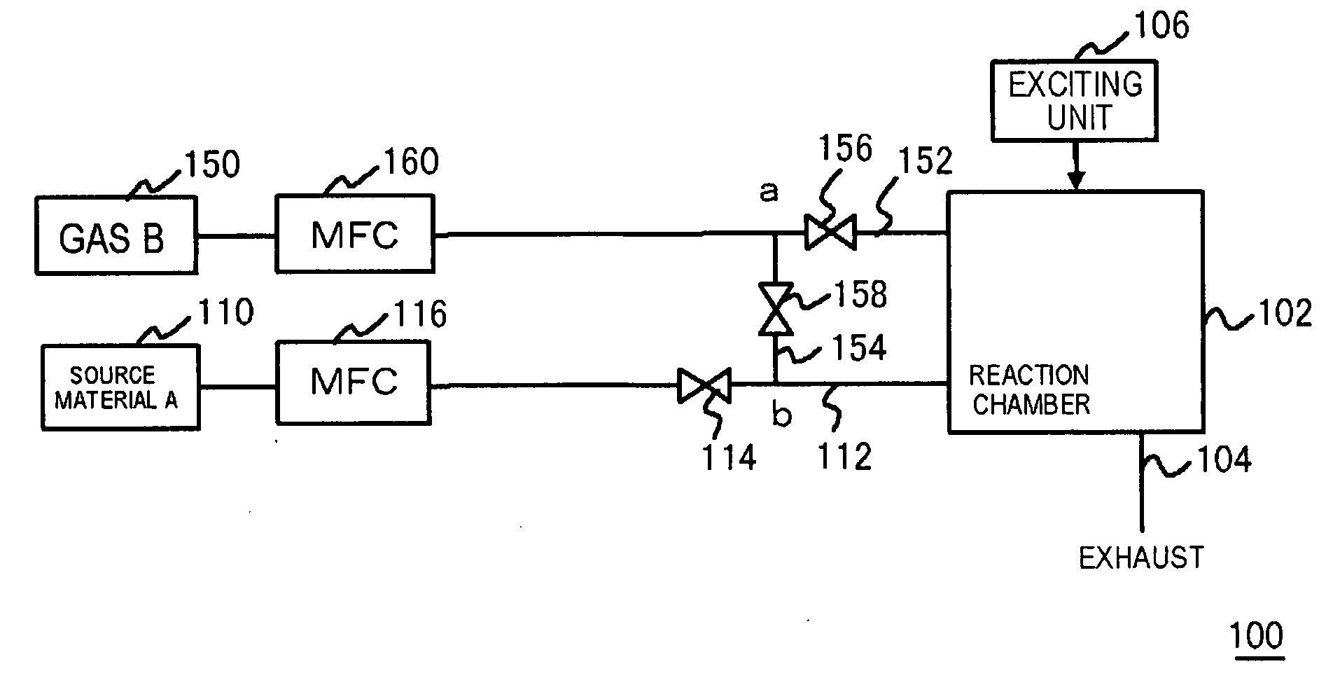
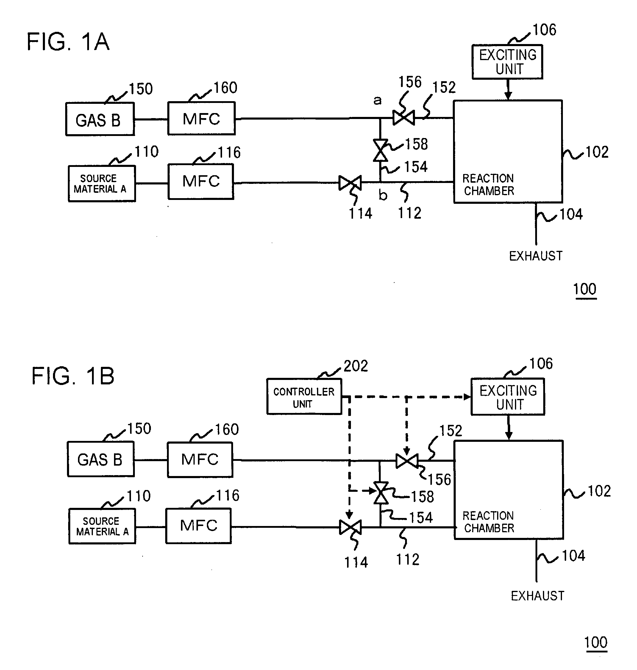
[0049]FIG. 1A is a diagram, illustrating a configuration of a deposition apparatus in the present embodiment. A deposition apparatus 100 includes: a reaction chamber 102 for depositing a film; an exciting unit 106 for exciting a gas to form a plasma; a first source material supplying unit 110 for supplying a first source material A; a first gas supply line 112; a gas supplying unit 150 for supplying a gas B (second gas); and a second gas supply line 152. The first source material A may be a gaseous material at an ambient temperature, or alternatively may be solid or liquid material at an ambient temperature. The deposition apparatus 100 may be configured that a first source material A can be vaporized and supplied into a reaction chamber 102 in the apparatus, even if the first source material A is liquid or solid material at an ambient temperature. A gas of the first source material A corresponds to the first gas described above.

[0050]The first gas supply line 112 and the second gas...

second embodiment

[0076]FIG. 6 is a diagram, illustrating an exemplary implementation of a configuration of a deposition apparatus in the present embodiment. The deposition apparatus 100 includes a reaction chamber 102, an exhaust line 104, an exciting unit 106, a first source material supplying unit 110, a first MFC 116, a gas supplying unit 150, a second MFC 160, a third source gas supply line 170, a fourth source gas supply line 172, a valve 174 (switching unit), a valve 176 (switching unit) and a controller unit 202.

[0077]The fourth source gas supply line 172 is connected to the reaction chamber 102 to supply the gas B to the reaction chamber 102. The valve 176 is provided in the fourth source gas supply line 172, and serves as implementing and stopping a supply of the gas B to the reaction chamber 102. In the present embodiment, the valve 176 is constantly opened during the depositing operation, and the gas B is continually supplied in reaction chamber 102. The third source gas supply line 170 i...


PUM

PropertyMeasurementUnit
Flow rateaaaaaaaaaa
Efficiencyaaaaaaaaaa

Abstract

An enhanced utilization efficiency of gases can be presented and an improved deposition characteristics are presented, when a film is deposited with a plurality of gases. A deposition apparatus 100 includes: a reaction chamber 102 for depositing a film; a first gas supply line 112 and a second gas supply line 152 for supplying a first source material A and a gas B to a reaction chamber 102, respectively; and an exciting unit 106 that is capable of exciting a gas supplied in the reaction chamber 102 to form a plasma. In the deposition apparatus 100 having such configuration, a deposition operation is performed by: a first operation for supplying a gas derived from a first source material A and a gas B in the reaction chamber 102 to cause the gas derived from a first source material A adsorbed on the substrate, thereby forming a deposition layer; and a second operation for supplying a second gas in reaction chamber 102, and treating the deposition layer with the gas in a condition of being plasma-excited.

Description

[0001]This application is based on Japanese patent application No. 2006-35,243, the content of which is incorporated hereinto by reference.BACKGROUND[0002]1. Technical Field[0003]The present invention relates to a deposition apparatus and method for depositing a film.[0004]2. Related Art[0005]In semiconductor devices of recent years, a delay in signal propagation through an interconnect restricts an operating speed of electronic elements. A delay constant in signal propagation through an interconnect is represented by a product of an interconnect resistance and an interconnect capacitance. Therefore, in order to achieve faster operation of elements, a low dielectric constant material having lower dielectric constant than a conventional silicon dioxide film (SiO2) is employed for an interlayer insulating film, and copper (Cu) having lower resistivity is employed for an interconnect.[0006]A multiple-layered interconnect employing copper as an interconnect material is formed by a damas...

Claims


Application Information

Patent Timeline
IPC IPC(8): C23C16/00
CPCC23C16/452C23C16/45525C23C16/515C23C16/45561C23C16/45542
Inventor FURUYA, AKIRA
Owner RENESAS ELECTRONICS CORP
Why Eureka
Try Eureka