Eureka AIR delivers breakthrough ideas for toughest innovation challenges, trusted by R&D personnel around the world.

Pressure control isolation and flood preventative tank for a hot water based heating system

a technology of pressure control and flood prevention, which is applied in the direction of hot water central heating, lighting and heating apparatus, heating types, etc., can solve the problems of system leakage, high price of glycol makeup systems, and extensive damage to the surrounding objects as well as the heating or cooling system

Inactive Publication Date: 2007-08-16
POLKHOUSKIY NIKOLAY
View PDF28 Cites 11 Cited by
  • Summary
  • Abstract
  • Description
  • Claims
  • Application Information

AI Technical Summary

Benefits of technology

"The present invention is a temperature control system that improves the art of closed loop heating systems. It aims to preserve the integrity of components, maintain fluid pressure, prevent leaks, and provide a safer barrier between heating system fluid and service water. The invention includes a pressure control isolation tank with a diaphragm that separates temperature control system fluid from non-system fluid, allowing the diaphragm to flex and change the ratio of the two volumes to maintain fluid pressure. The tank also includes a drain orifice and a fill orifice for adding fluid, as well as a shutoff device and alarm to alert when the temperature control system fluid level is low. The invention also includes a visual alarm to indicate the fluid level, a reed switch to trigger the shutoff device, and a layer of air between the upper and lower diaphragms to allow for easy inspection of any leaks. Overall, the invention provides a more reliable and efficient heating system and ensures safety and integrity of the system."

Problems solved by technology

However, these glycol makeup systems are expensive and thus usually limited mostly to commercial and industrial applications.
There are some problems inherent in this system.
First, where the hot water system incurs a significant leak, the pressure reducing valve feeds the system with water from the water supply so that the fluid, water, antifreeze or combination thereof leaks from the system until somebody notices such leak.
The leak can cause extensive damage to the building, surrounding objects as well as to the heating or cooling system.
Second, due the air venting and the tiny or significant fluid leaking, the system containing antifreeze is constantly diluted with water from the water supply via feeding the pressure reducing valve whether the system operates normally or the system incurs a significant leak.
Such dilution leads to freezing and bursting heating system components such as water lines, radiators, etc, which are expensive to repair.
Third, where water fed to the heating system from the water supply is hard, containing certain minerals, such as lime, sulphur, etc., the pressure reducing valve as well as other heating system components become corroded due the presence of the minerals.
This corrosion, as a rule, leads to seizing of the pressure reducing valve in an open or closed position and the pressure cannot anymore be controlled by the valve thus resulting in an underpressurized or overpressurized system.
Both conditions have serious negative consequences for the system and its surrounding items.
Fourth, when for any reason the pressure in the service water supply drops below a certain level, typically below 12 PSI, and a check valve or backflow preventer fails, system fluid which could contain antifreeze backflows into the service water supply, thus affecting the household drinking water.
Fifth, the system containing antifreeze and pressurized by a pressure reducing valve is cumbersome to service.
Charging antifreeze back into the system and purging air pockets requires a portable pump and often a significant amount of time.
Because of the relatively high cost of the pump, the pump is often not available for a technician on call.
Thus, the technician usually just adds more water into the system which leads to all of the negative consequences of the diluted fluid.
However, this requires constant monitoring which is not convenient.

Method used


Image

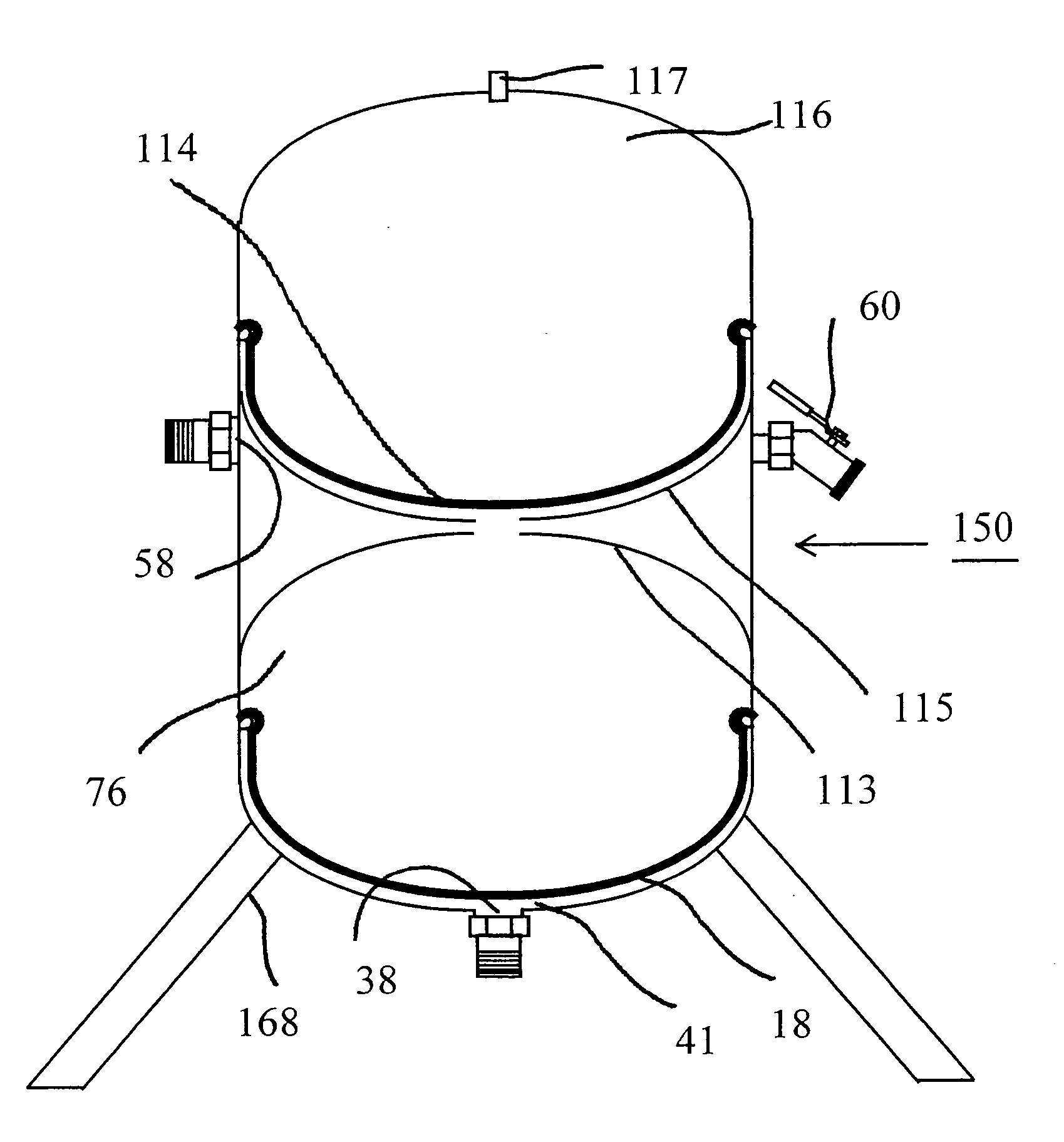
  • Pressure control isolation and flood preventative tank for a hot water based heating system
  • Pressure control isolation and flood preventative tank for a hot water based heating system
  • Pressure control isolation and flood preventative tank for a hot water based heating system

Examples


Embodiment Construction

[0047] The present invention shall now be described in accordance with a number of varying embodiments, although care should be taken not to limit the scope of the invention to those embodiments, but must be determined according the claims that follow herein.

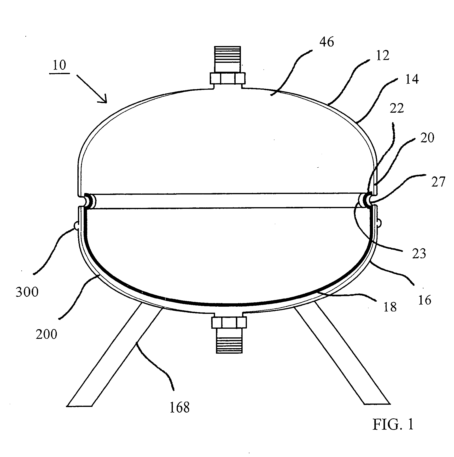
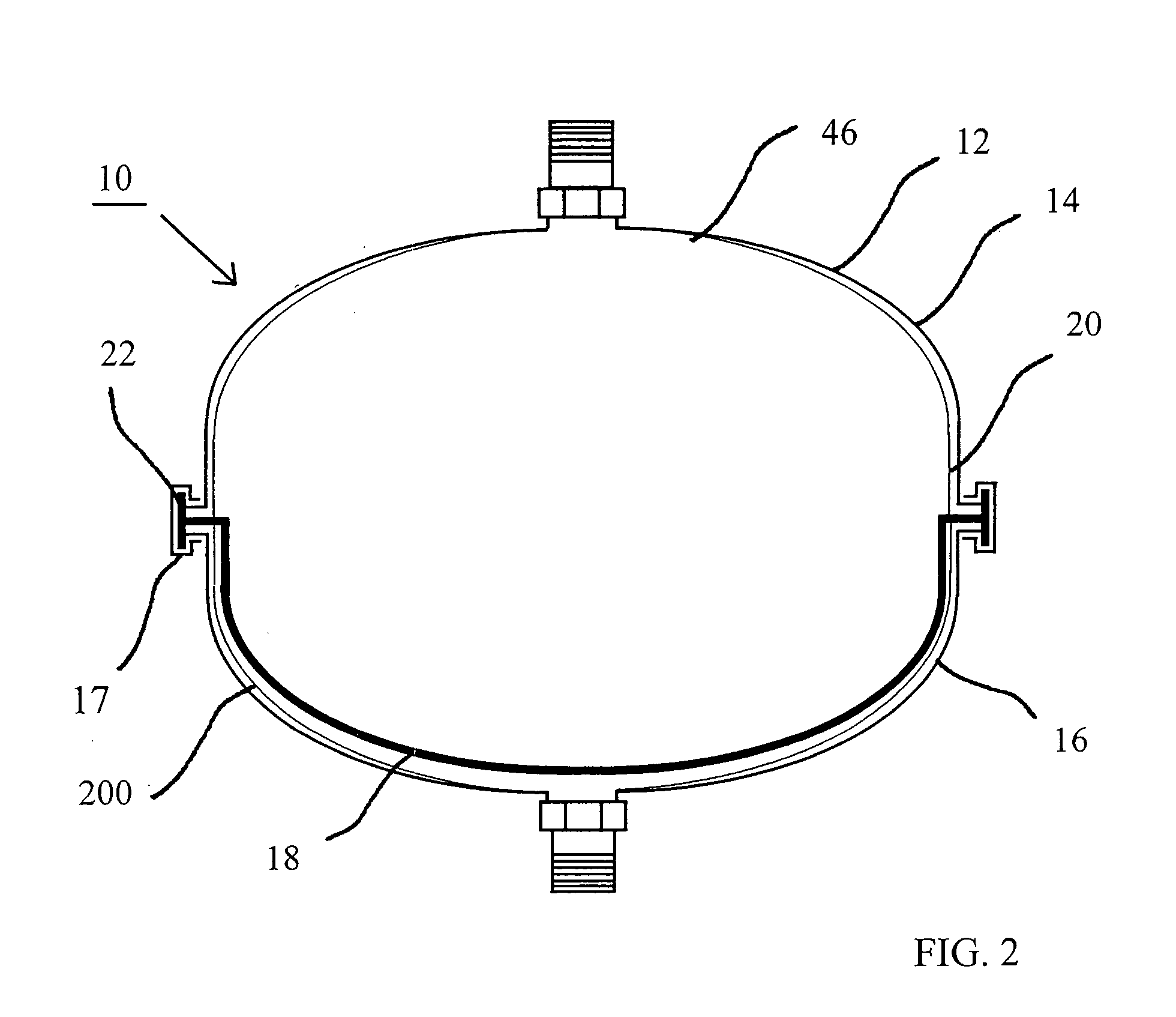
[0048] Referring now to FIG. 1, there is shown a pressure control isolation tank 10 for a closed loop heating, namely a hot water based heating system, in which the pressure control isolation tank 10 prevents an interchange between fluid of the heating system and the service supply water and also helps maintain a constant pressure within the heating system fluid. The heating system fluid is typically hot water, antifreeze of a combination thereof.

[0049] The pressure control isolation tank 10 has a desirable feature of preventing a major flood in the event of a rupture within the heating system. In the event of a leak, the heating system fluid leaks from the system through the rupture. However, service water cannot escape throu...


PUM


Abstract

The present invention provides a pressure control isolation tank for a closed loop heating system. A diaphragm within the tank separates heating system fluid from non-system fluid. The heating system fluid is provided under constant pressure, typically 12 PSI. Usually the non-system fluid is service water or clean water flowing through a pressure reducing valve. As the heating system loses system fluid through tiny leaks, and also loses air through vents, the non-system fluid causes the diaphragm to displace the volume lost by the leaked heating system fluid and leaked air. Thus, the heating system fluid is maintained at a constant pressure.

Description

FIELD OF THE INVENTION [0001] The present invention relates generally to the field of fluid based temperature control systems and, more particularly, to a pressure control isolation tank that keeps a constant fluid pressure within a hot water heating system. BACKGROUND OF THE INVENTION [0002] There are many types of hot water based heating systems, which use water, antifreeze or a combination thereof. These hot water based heating systems include, but are not limited to, baseboard and cast iron radiator systems, in-floor radiant heating systems, in-sidewalk radiant heating systems, solar heating systems each of which contain fluids under pressure. [0003] It is well known that during operation of the hot water heating systems, air in the heating system separates from water and is typically vented into the atmosphere through automatic vents installed throughout the system. It is also a fact that tiny invisible leaks of the fluid may occur in the hot water heating system through thread...

Claims


Application Information

Patent Timeline
Patent Type & Authority Applications(United States)
IPC IPC(8): F24H9/20
CPCF24D3/1016F24D3/1008
Inventor POLKHOUSKIY, NIKOLAY
Owner POLKHOUSKIY NIKOLAY
Why Eureka
Eureka Blog
Learn More