Fuel cell, fuel cell system and electronic device

a fuel cell and fuel cell technology, applied in the field of fuel cell, fuel cell system and electronic device, can solve the problems of difficult separation between liquid fuel and exhaust gas generated at the anode, complex system, and leakage of liquid fuel such as aqueous methanol solution from gas discharge hole, and achieve stable and good power generation characteristics and good safety

Inactive Publication Date: 2015-06-16
SHARP KK
View PDF83 Cites 0 Cited by
  • Summary
  • Abstract
  • Description
  • Claims
  • Application Information

AI Technical Summary

Benefits of technology

[0030]It is an object of the invention to solve the above problems and to provide a fuel cell having stable and good power generation characteristics and having good safety, a fuel cell system including the fuel cell and an electronic device equipped with the fuel cell.
[0031]The invention is directed to a fuel cell including at least an electrolyte membrane, an anode formed on one surface of the electrolyte membrane, a cathode formed on another surface of the electrolyte membrane, a liquid fuel chamber for supplying a liquid fuel to the anode, and a separating layer formed between the anode and the liquid fuel chamber, wherein the separating layer and / or the anode has an exhaust passage that is continuously formed in an in-plane direction to discharge exhaust gas generated at the anode, and the separating layer allows the liquid fuel to pass from the liquid fuel chamber to the anode and blocks the movement of gas from the anode to the liquid fuel chamber.
[0052]In the fuel cell of the invention, the exhaust gas generated at the anode is allowed to move in the in-plane direction through the exhaust passage of the separating layer and / or the anode and discharged out of the fuel cell. Therefore, even when a high concentration liquid fuel is supplied, the liquid fuel can be prevented from leaking, contamination of the liquid fuel with exhaust gas generated at the anode can also be prevented, and stable and good power generation characteristics and good safety can also be provided. According to the invention, the structure for discharging exhaust gas in the in-plane direction can prevent contamination of the liquid fuel supply route with the exhaust gas generated at the anode, even when a positional deviation occurs during fuel cell assembling or when shaking is caused by transportation, so that stable and good power generation characteristics and good safety can be provided. Fuel cell systems including the fuel cell of the invention have stable and good power generation characteristics and also have good safety. There are also provided electronic devices that are equipped with the above fuel cell and have stable and good power generation characteristics and good safety.
[0053]The fuel cell of the invention using a high concentration liquid fuel can have stable and good power generation characteristics and good safety, even when a positional deviation occurs during assembling or when shaking is caused by transportation. The fuel cell of the invention and the fuel cell system including the fuel cell are suitable for use in electronic devices, particularly portable electronic devices such as mobile devices.

Problems solved by technology

In this case, however, there is a problem in which the liquid fuel such as an aqueous methanol solution can leak from the gas discharge hole.
However, the structure disclosed in Japanese Patent Laying-Open No. 2000-106201 has a problem in which if a high concentration fuel is used, the discharge of carbon dioxide to the outside of the fuel cell can be accompanied by the discharge of the high concentration gaseous fuel.
However, the configuration disclosed in Japanese Patent Laying-Open No. 2005-032600 still has a problem in which the system is complicated, and separation between the liquid fuel and exhaust gas generated at the anode is difficult.
However, the structure of Japanese Patent Laying-Open No. 2001-102070 causes a problem, for example, in a case where an aqueous methanol solution is charged into the introducing tube.
Therefore, there is a problem in which the aqueous methanol solution can leak out of the fuel cell due to the increase in the internal pressure of the introducing tube, even if the surface of the pores in the porous separation membrane is water-repellent treated with a fluororesin.
There is also a problem in which when an aqueous methanol solution with a high concentration is supplied to the introducing tube, the aqueous methanol solution can infiltrate into the separation membrane because of a surface tension of methanol lower than that of water, so that the separation membrane cannot perform its own function, even if the surface of the pores in the porous separation membrane is water-repellent treated.
However, the method of Japanese Patent Laying-Open No. 2003-331899 has a problem in which even if the gas-liquid separation membrane is oil-repellent treated, an aqueous methanol solution with a high concentration in contact with the gas-liquid separation membrane can infiltrate into the membrane so that the function of the gas-liquid separation membrane can be easily degraded.
There is also a problem in which if operation for power generation is performed in an orientation where carbon dioxide less comes into contact with the gas-liquid separation membrane, for example, if the positive electrode is placed upward in the vertical direction, carbon dioxide generated at the negative electrode can increase the internal pressure of the liquid storing part until it comes into contact with the gas-liquid separation membrane so that the aqueous methanol solution can leak from the gas-liquid separation membrane to the outside of the fuel cell.
However, the structure disclosed in Japanese Patent Laying-Open No. 2002-175817 has a problem in which as disclosed in its specification, if a deviation is caused between the positions of the stacked liquid fuel supply channel and fuel permeable member by an insufficient location accuracy in fuel cell assembling or by shaking during transportation, carbon dioxide gas can be discharged to the liquid fuel supply channel, or the liquid fuel can leak to the gas discharge channel, so that separation between the aqueous methanol solution and carbon dioxide gas can be difficult.
Thus, there is a problem in which if the fuel permeable member is dissociated from the anode catalyst layer, carbon dioxide gas can stay at the interface between the fuel permeable member and the anode catalyst layer to inhibit the liquid fuel supply to the anode catalyst layer.
Thus, the fuel cell still has a problem in which the fuel can finally leak outside the fuel cell, when carbon dioxide is discharged with a liquid waste tank or the like.
The technique of Japanese Patent Laying-Open No. 2004-206885 has a problem in which the exhaust hole for carbon dioxide generated by the reaction also serves as an injection hole for the liquid fuel, so that separation between exhaust gas generated at the anode and the liquid fuel is difficult, and also has another problem in which the liquid fuel supply efficiency can be easily reduced by the contamination of the liquid fuel with carbon dioxide, and when the liquid fuel is distributed to the whole, the structure for discharging carbon dioxide in the layer thickness direction of the fuel cell makes the liquid fuel travel a long distance, so that the pressure loss can be increased when the fuel is supplied.

Method used


Image

  • Fuel cell, fuel cell system and electronic device
  • Fuel cell, fuel cell system and electronic device
  • Fuel cell, fuel cell system and electronic device

Examples


embodiment 1

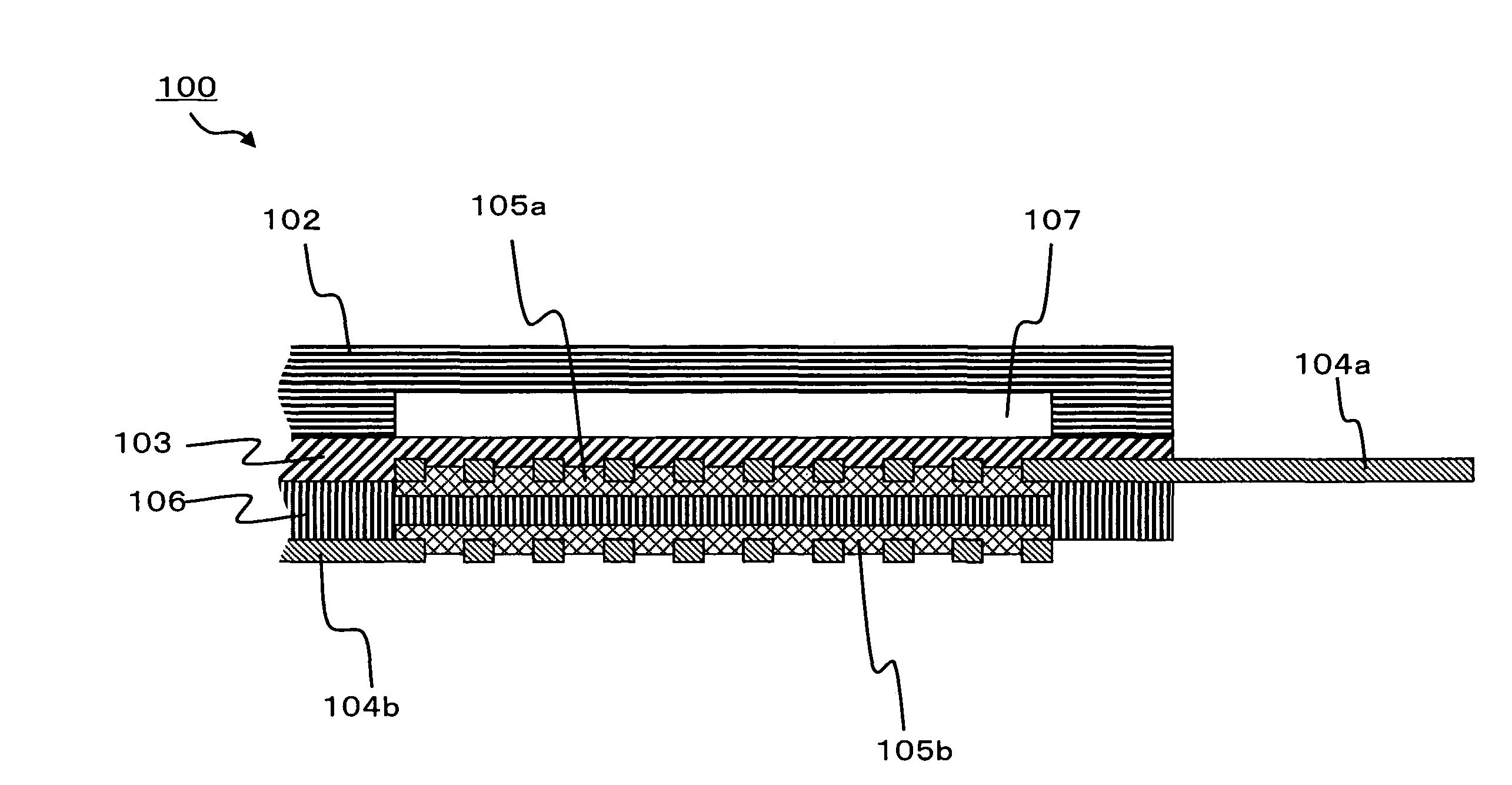
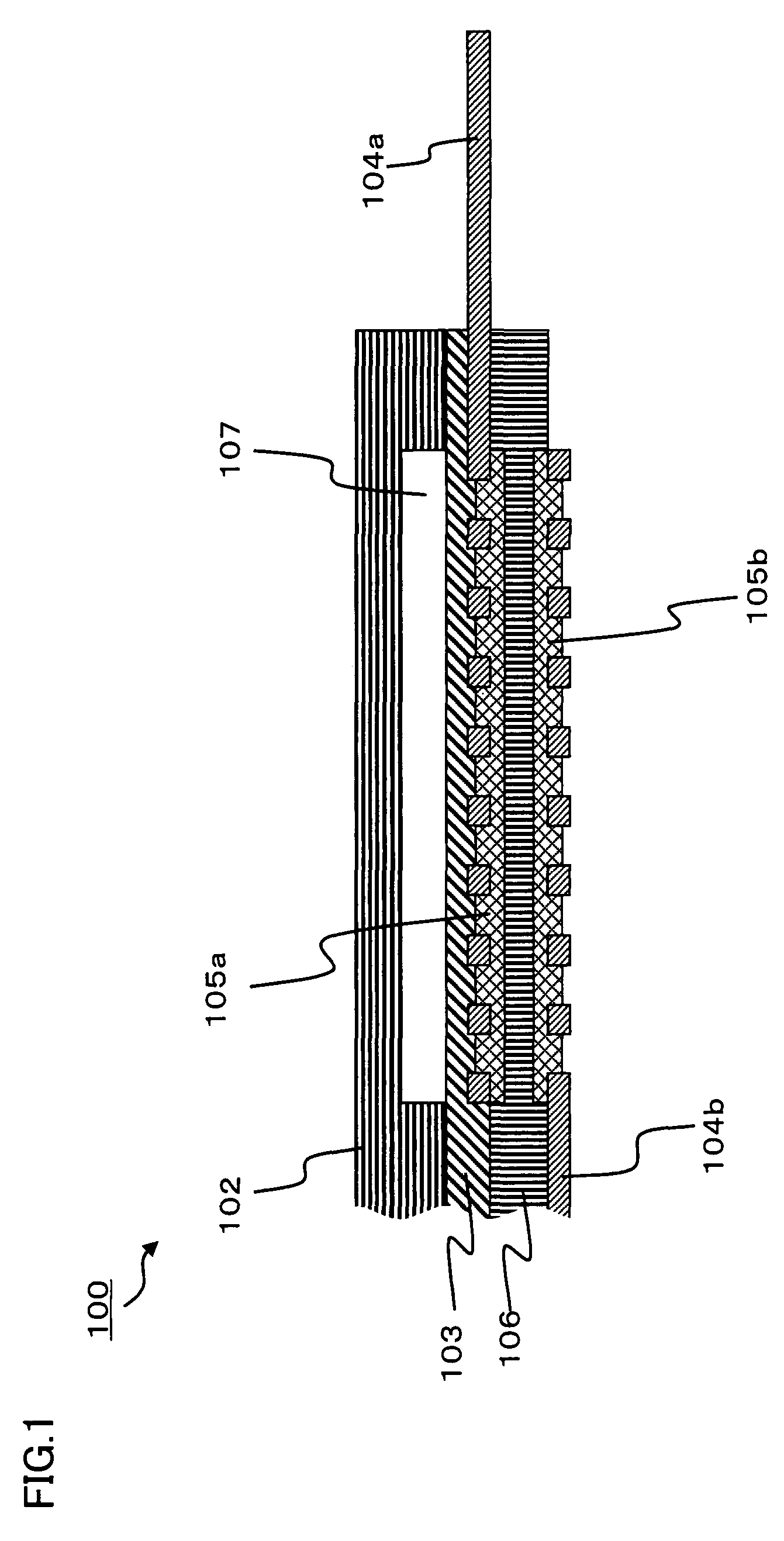
[0086]Referring to FIG. 1, a fuel cell 100 includes an anode composed of an anode conductive layer 104a and an anode catalyst layer 105a, an electrolyte membrane 106, a cathode composed of a cathode catalyst layer 105b and a cathode conductive layer 104b, a separating layer 103 provided in contact with the anode, and a housing 102. Housing 102 is sealed with separating layer 103 to form a liquid fuel chamber 107. Anode catalyst layer 105a is typically composed of an electrolyte and an anode catalyst-supporting electrical conductor including anode catalyst particles supported by an anode conductor.

[0087]According to the invention, separating layer 103, which allows the liquid fuel to pass from the liquid fuel chamber to the anode and blocks the movement of gas from the anode to the liquid fuel chamber, selectively allows the liquid fuel to pass through in the thickness direction of the separating layer and hardly allows the exhaust gas generated at the anode to pass through. FIG. 1 s...

embodiment 2

[0117]FIG. 3 shows a case where an exhaust passage is formed in a housing. In the invention, if it is difficult to discharge exhaust gas outside the fuel cell by allowing the exhaust gas to move inside the pores in anode conductive layer 104a, an exhaust passage 109 should preferably be formed in a part of housing 102 so as to be in contact with anode conductive layer 104a in a fuel cell 300 configured as shown in FIG. 3. In this structure, the exhaust gas generated at the anode can be immediately discharged out of the fuel cell. In this case, in order to obtain a strong junction between housing 102 and electrolyte membrane 106, the pores in anode conductive layer 104a may be filled with a gas impermeable sealant 110. Also in such a structure, the exhaust gas can be discharged out of the fuel cell through exhaust passage 109.

[0118]Electrically-Conductive Layer (Conductive Layer)

[0119]The liquid fuel supplied from liquid fuel chamber 107 passes through separating layer 103 and reache...

embodiment 3

[0149]FIG. 5 shows a case where the anode conductive layer is joined to the electrolyte membrane. In the invention, if only a material completely soluble in the liquid fuel is used as the electrolyte, it can become impossible to maintain the shape of anode catalyst layer 205a. Thus, the anode conductive layer is preferably joined to the electrolyte membrane, as represented by anode conductive layer 104a and electrolyte membrane 106 in the structure of a fuel cell 500 shown in FIG. 5. In this case, even when electrolyte 209 in anode catalyst layer 205a is dissolved so that it becomes difficult to maintain the shape of anode catalyst layer 205a, the dissociation between anode catalyst layer 205a and electrolyte membrane 206 can be suppressed so that stable power generation characteristics can be maintained in the fuel cell, because separating layer 203, anode conductive layer 204a and electrolyte membrane 206 are joined.

[0150]Anode catalyst particles 211 function as a catalyst for the...


PUM

PropertyMeasurementUnit
temperatureaaaaaaaaaa
depthaaaaaaaaaa
widthaaaaaaaaaa

Abstract

There are provided a fuel cell having stable and good power generation characteristics and good safety, a fuel cell system including the fuel cell and an electronic device equipped with the fuel cell. The fuel cell includes at least an electrolyte membrane, an anode formed on one surface of the electrolyte membrane, a cathode formed on the other surface of the electrolyte membrane, a liquid fuel chamber for supplying a liquid fuel to the anode, and a separating layer formed between the anode and the liquid fuel chamber. The separating layer and / or the anode has an exhaust passage that is continuously formed in an in-plane direction to discharge exhaust gas generated at the anode. The separating layer allows the liquid fuel to pass from the liquid fuel chamber to the anode and blocks the movement of gas from the anode to the liquid fuel chamber.

Description

[0001]This nonprovisional application is based on Japanese Patent Applications Nos. 2006-157511 and 2007-051642 filed with the Japan Patent Office on Jun. 6, 2006 and Mar. 1, 2007, respectively, the entire contents of which are hereby incorporated by reference.BACKGROUND OF THE INVENTION[0002]1. Field of the Invention[0003]The invention relates to a fuel cell having stable and good power generation characteristics and having good safety, a fuel cell system including the fuel cell and an electronic device equipped with the fuel cell.[0004]2. Description of the Background Art[0005]In recent years, expectations have been growing for fuel cells, because they can provide efficient power sources for portable electronic devices supporting information-oriented society and provide efficient stand-alone power generation devices. In a fuel cell, a fuel and oxygen from the air are electrochemically oxidized and reduced at an anode and a cathode, respectively, and electric power is generated thr...

Claims


Application Information

Patent Timeline
Patent Type & Authority Patents(United States)
IPC IPC(8): H01M8/02H01M8/04H01M8/10
CPCH01M8/1011H01M8/04201Y02E60/523Y02E60/50
Inventor YOSHIE, TOMOHISAOCHI, NORIHIROSAITOH, KOHTAROHKANBARA, HIRONORIGOTOH, YASUYOSHI
Owner SHARP KK
Why Eureka
Try Eureka