Rock drill water separator

a technology of dust suppression apparatus and rock drill, which is applied in the direction of fluid removal, earth-moving drilling, and well accessories, etc. it can solve the problems of affecting the environment, workers and mechanical equipment, and wear on the cutting services, and achieve the effect of facilitating water evacuation

Inactive Publication Date: 2007-08-16
BRODIE JOHN +2
View PDF2 Cites 4 Cited by
  • Summary
  • Abstract
  • Description
  • Claims
  • Application Information

AI Technical Summary

Benefits of technology

[0006] According to the present invention there is disclosed a dewatering module adapted to be inserted between a rock drill bit and a drill string comprising an outer housing and having a first end remote from the drill bit and a second end adapted to lie immediately adjacent the drill bit; an air/water inlet at the first end of the module adapted to receive a high pressure composite air and water flow from within the drill string and to deliver said flow into a main chamber within the module; an inner tubular housing within the chamber defining a passage within the chamber from its first and inlet end adjacent the air/water inlet to its outlet and second end at the drill bit; the first and inlet end of the inner housing being shielded by a first baffle from the composite air water flow entering the chamber; the first baffle comprising a...

Problems solved by technology

Typically this evacuation of debris laden air creates enormous volumes of dust which adversely effect the environment, workers and mechanical equipment.
Whereas it is important that the air reaches the cutting face at the front of the drill bit is und...

Method used


Image

  • Rock drill water separator
  • Rock drill water separator
  • Rock drill water separator

Examples


Embodiment Construction

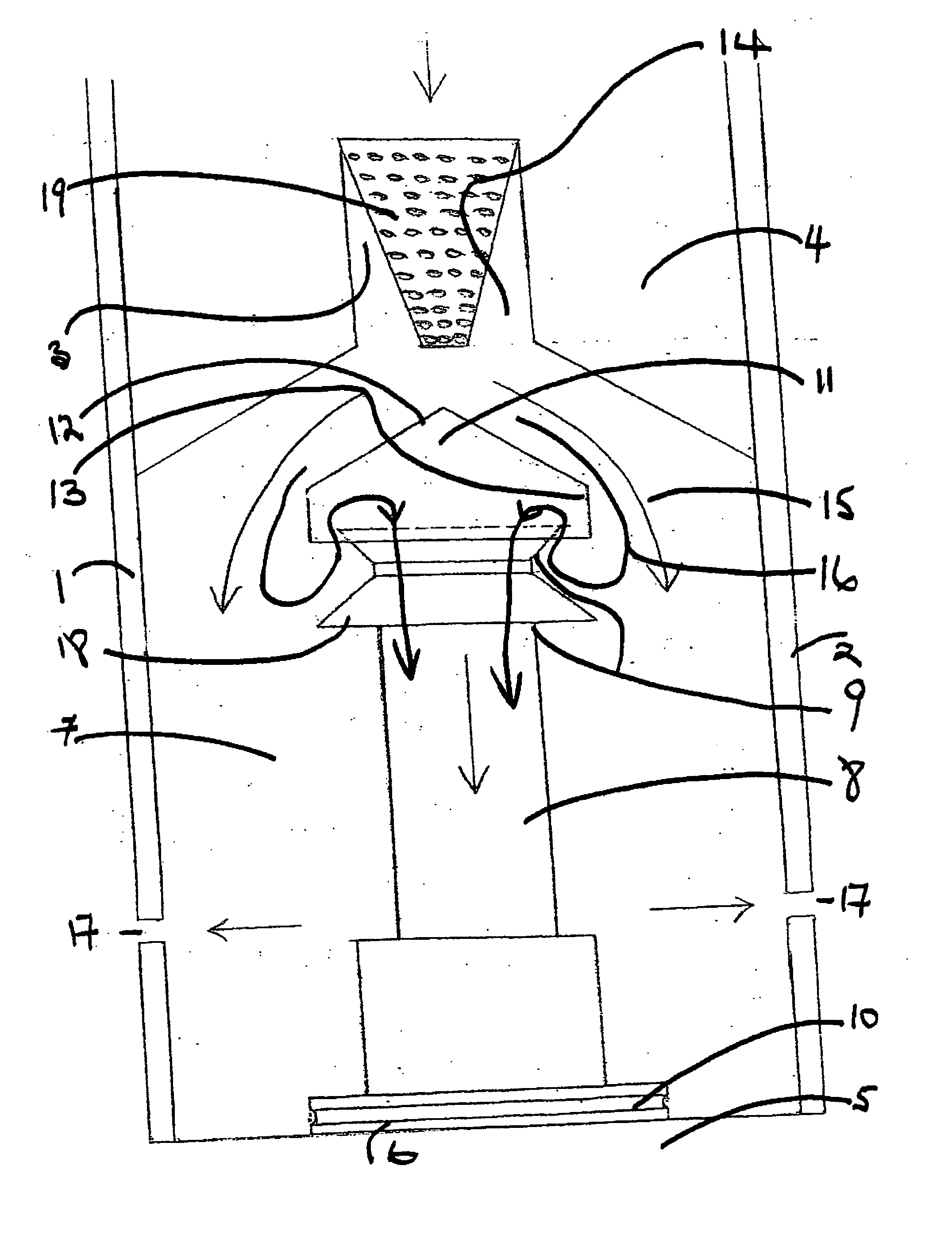
[0010] According to the embodiment of FIG. 1 there is disclosed a dewatering module 1 comprising an outer tubular housing 2 and an air / water inlet 3 adjacent first end 4 thereof. The second end 5 of the module is adapted to receive a drill bit (not shown) in a standard mount 6.

[0011] The module 1 defines a chamber 7 which in turn contains an inner tubular housing 8 extending from a first inlet end 2 to a second outlet end 10 adjacent the drill bit (not shown). The inlet end 9 of inner tubular housing 8 is covered by baffle 11 comprising conical hat portion 12 and depending skirt portion 13. It will be observed that the diameter of depending skirt 13 is greater than that of the inlet 9 to inner tubular housing 8 hence allowing passage of air between the skirt and the outer and upper extremities of tubular housing 8.

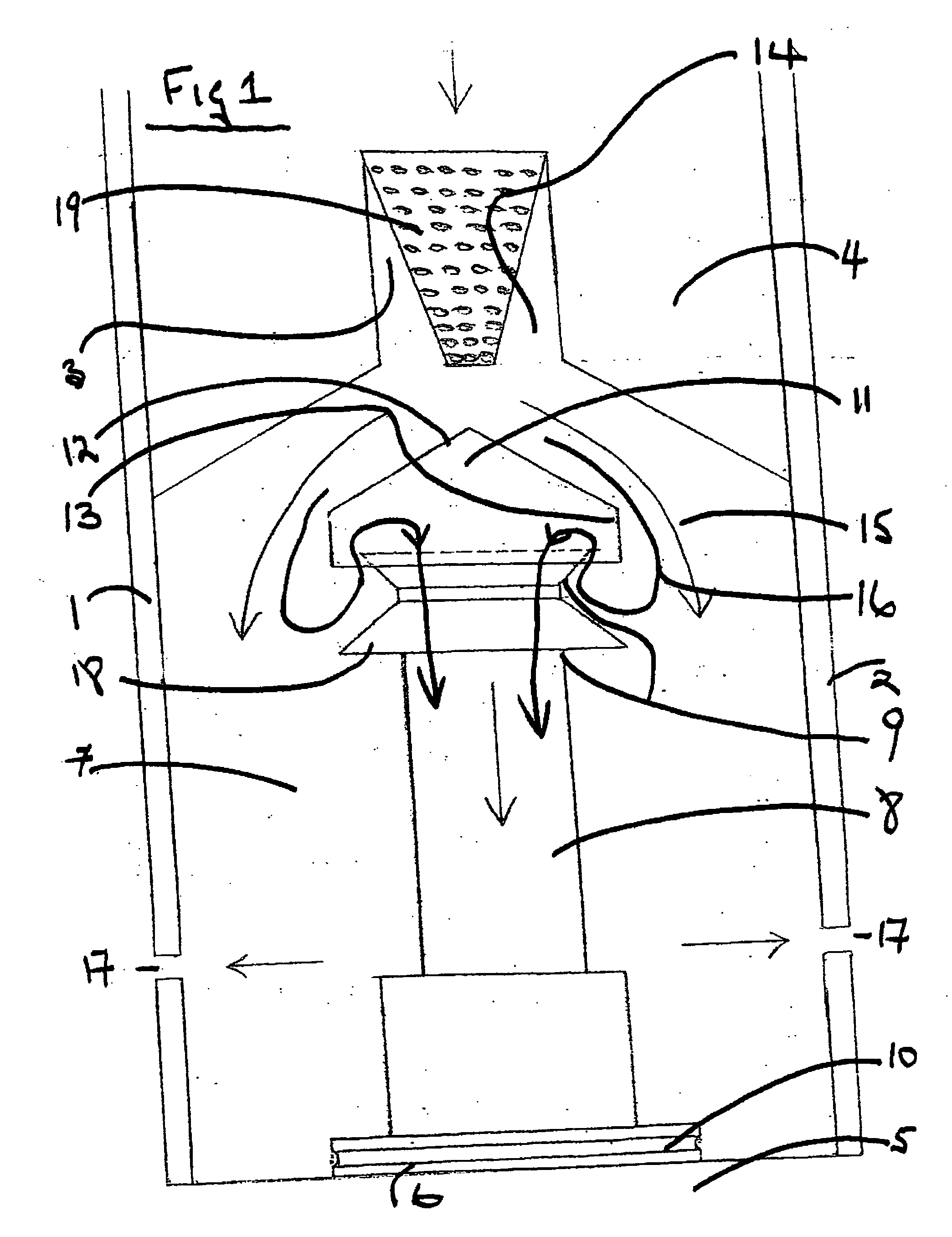
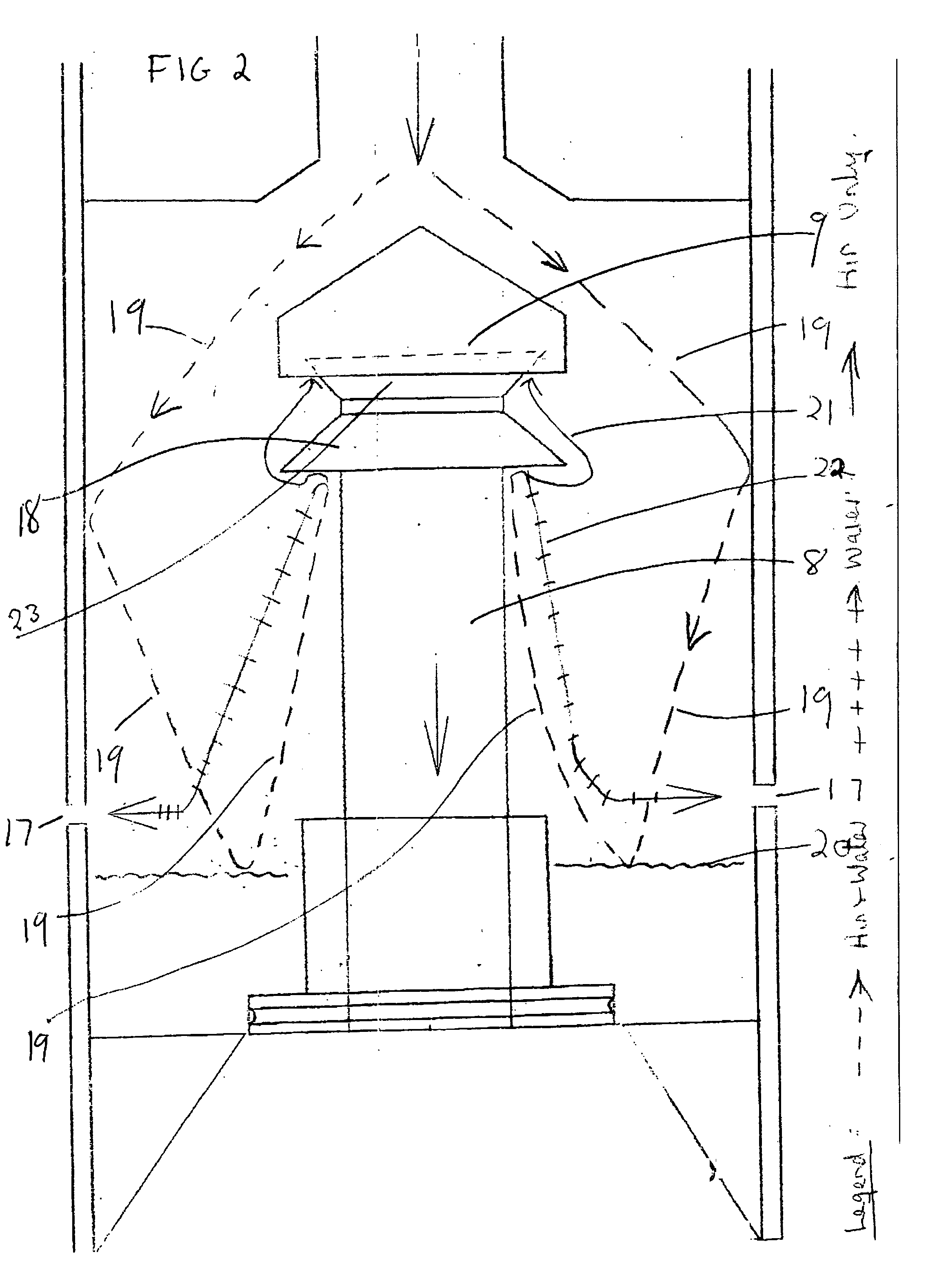
[0012] In use the module operates by receiving a pressurised air / water flow through inlet 3 in the direction indicated by arrow 14. This flow is directed onto the centre...


PUM


Abstract

A dewatering module adapted to be inserted between a rock drill bit and a drill string comprising an outer housing and having a first end remote from the drill bit and a second end adapted to lie immediately adjacent the drill bit; an air/water inlet at the first end of the module adapted to receive a high pressure composite air and water flow from within the drill string and to deliver said flow into a main chamber within the module; an inner tubular housing within the chamber defining a passage within the chamber from its first and inlet end adjacent the air/water inlet to its outlet and second end at the drill bit; the first and inlet end of the inner housing being shielded by a first baffle from the composite air water flow entering the chamber; the first baffle comprising a deflector overlying the first and inlet end of the inner housing and having a skirt being of larger diameter than the tubular inner housing inlet such that air entering the inner housing is forced to reverse direction and traverse an “S” shaped path to enter the inner housing before traveling therethrough to the drill bit; a second laterally extending separator baffle beneath the skirt of the first baffle located such that and being of a diameter adequate to prevent direct entry into the inlet of an air/water stream deflected from the base of the main chamber upwardly towards the inlet of the inner housing; holes in the sides of the outer housing remote from the air/water inlet and baffle and adjacent its second end to facilitate evacuation of water from the chamber and into the area where debris from the drilling operation is being exhausted.

Description

FIELD OF THE INVENTION [0001] The present invention relates to rock drill dust suppression apparatus and in particular to a unit adapted to sit behind the drill bit and separate water from the composite air and water stream commonly directed through rock drill strings towards drill bits. BACKGROUND OF THE INVENTION [0002] Typically rock drills such as are utilised to create bores in which to place explosive charges comprise a drill bit mounted at the forward end of a drill string which string consists of sections joined together by appropriate connectors. In order to assist in evacuation of debris created by the action of the drill bit on the rock air is delivered at high pressure through a bore of the drill string to the drill bit. This air then exhausts with debris back up the hole being created by the drill between the drill string and the sides of the hole being drilled. [0003] Typically this evacuation of debris laden air creates enormous volumes of dust which adversely effect ...

Claims


Application Information

Patent Timeline
IPC IPC(8): E21B27/00
CPCE21B21/14E21B21/002
Inventor BRODIE, JOHNEVANS, GRAEMEJUON, NICHOLAS
Owner BRODIE JOHN
Why Eureka
Try Eureka