Seal with controllable pump rate

a technology of dynamic shaft and pump rate, which is applied in the direction of engine seals, mechanical equipment, engine components, etc., can solve the problems of static oil leakage, potential problems, and lubricant may leak from the lubricated side to the non-lubricated side, and achieve the effect of increasing the fluid pressure in the groov

Active Publication Date: 2007-08-16
FREUDENBERG NOK GEN PARTNERSHIP
View PDF49 Cites 13 Cited by
  • Summary
  • Abstract
  • Description
  • Claims
  • Application Information

AI Technical Summary

Benefits of technology

[0006] In one aspect of the present invention, a dynamic seal includes a lubricant side and a non-lubricant side. A sealing portion is operable to engage with and seal against a shaft. The sealing portion includes an active surface communicating with the non-lubricant side and a seal lip at an end thereof. The seal lip faces the lubricant side and defines an opening in which a shaft can be disposed. The active surface is operable to engage with and seal against a shaft disposed in the opening. There is at least one pumping element extending along the active surface and stopping short of the seal lip. The pumping element has a beginning point and a termination point. The pumping element is operable to capture lubricant that leaks past the seal lip and pump the lubricant toward the termination point and back into the lubricant side due to relative rotation between the active surface and a shaft.
[0007] In another aspect of the present invention, another dynamic seal is disclosed. The dynamic seal has both a lubricant side and a non-lubricant side. An active surface is operable to seal against a shaft. At least one groove extends along the active surface from the non-lubricant side toward the lubricant side with a portion of the active surface disposed between the groove and the lubricant side. The groove is operable to capture lubricant that leaks between the active surface and the shaft and pump captured lubricant into the lubricant side past the portion of the active surface. A first portion of the groove has a first characteristic. A second portion of the groove has a second characteristic different than the first characteristic. The second portion of the groove is closer to the lubricant side than the first portion of the groove.
[0008] In still another aspect of the present invention, a method of returning lubricant that leaks past a dynamic seal on a shaft back to a lubricant side of the seal is disclosed. The method includes: (1) capturing lubricant that leaks past the seal in a groove on an active surface of the seal, the groove stopping short of the lubricant side of the seal; (2) pumping the captured lubricant in the groove back toward the lubricant side of the seal; (3) increasing a fluid pressure in the groove as the groove approaches the lubricant side of the seal; (4) lifting a portion of the seal adjacent the lubricant side off of the shaft with the fluid pressure in the groove; and (5) returning captured lubricant in the groove back to the lubricant side of the seal through a gap between the lifted-off portion of the seal and the shaft.
[0009] Further areas of applicability of the present invention will become apparent from the detailed description provided hereinafter. It should be understood that the detailed description and specific examples, while indicating the preferred embodiment of the invention, are intended for purposes of illustration only and are not intended to limit the scope of the invention.

Problems solved by technology

Lubricant may, however, leak from the lubricated side to the non-lubricated (air) side through the interaction of the active surface of the seal with the shaft.
Having the grooves open at the oil side of the seal creates potential problems.
For example, static oil leaks can develop.
Additionally, air leakage during pressurization testing of the machinery on which the seal is being used at the end of the assembly stage can also occur.
Blocking the exit point on the oil side, however, reduces the pump rate so significantly that the seal performance degrades and makes the use of such a seal impractical and / or impossible.
Doing so reduces the pump rate also, but not to the extent where the seal performance degrades too much.
This blockage, however, does lead to other difficulties.
The most pronounced difficulty is oil stagnation close to the exit point.
This in turn leads to oil coking in the groove and eventually to seal failure.

Method used


Image

  • Seal with controllable pump rate
  • Seal with controllable pump rate
  • Seal with controllable pump rate

Examples


Embodiment Construction

[0019] The following description of the preferred embodiment(s) is merely exemplary in nature and is in no way intended to limit the invention, its application, or uses.

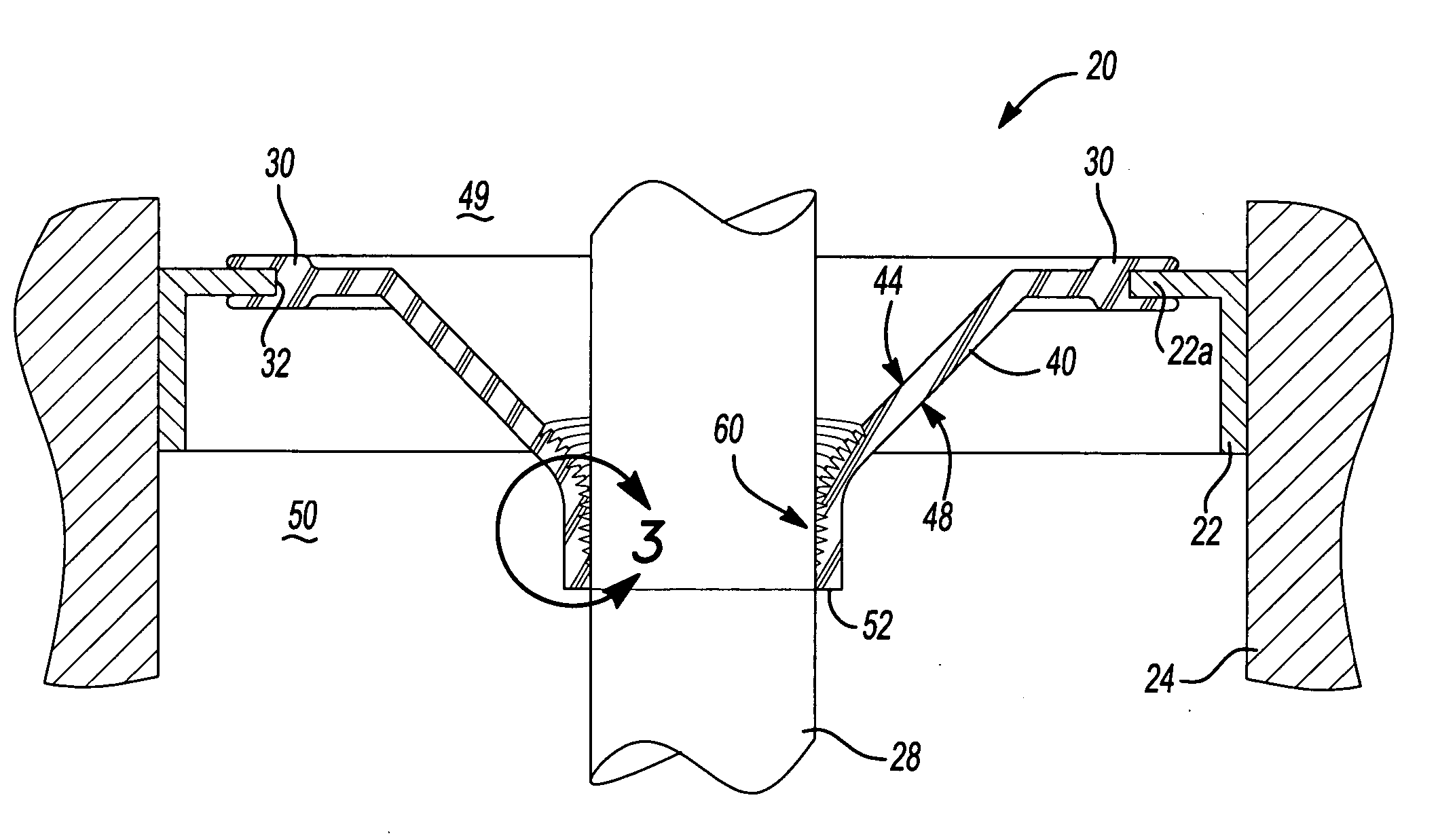
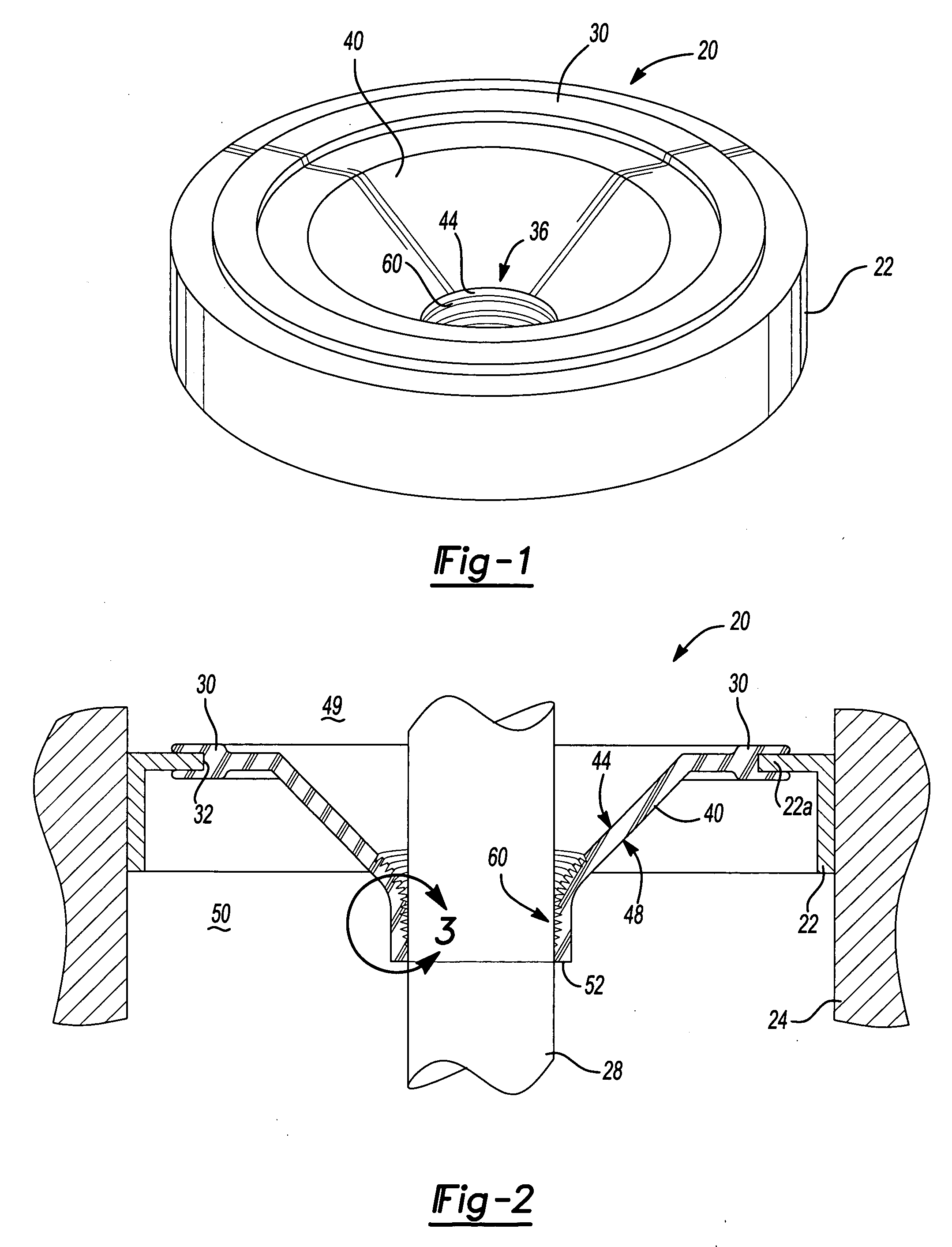
[0020] With reference to FIGS. 1-3, a dynamic seal 20 according to the preferred embodiment of the present invention is shown. Seal 20 is mounted to a casing 22 which is disposed in a fixed housing 24 (best shown in FIG. 2) in a manner which is well known in the art. Seal 20 engages a rotary shaft 28 and provides a sealed relationship between rotary shaft 28 and housing 24 in which casing 22 is disposed. With reference to FIG. 2, seal 20 includes a mounting portion 30 having an annular recess 32 therein. A mounting portion 22a of casing 22 resides within annular recess 32. It should be noted that mounting portion 30 and casing 22 can take on many shapes and forms and are not considered to be particularly relevant to the present invention. Mounting portion 30 is mounted to casing 22 which can be made of plastic or me...


PUM


Abstract

A dynamic seal advantageously utilizes a groove on the active side or surface of the seal to capture a leaked lubricant and hydrodynamically pump the lubricant back into the lubricated side of the seal. The groove stops short of the leading edge of the seal that faces the lubricant side thereby forming a static dam between the termination point of the groove and the seal edge. When the fluid pressure within the groove adjacent the static dam exceeds the opening pressure for the seal lip, the lubricant within the groove is pumped back into the lubricant side of the seal. The groove can have an induction zone wherein the fluid pressure rise is gradual and a booster zone wherein the fluid pressure rise is relatively faster than in the induction zone. The booster zone is disposed adjacent the static dam.

Description

FIELD OF THE INVENTION [0001] The present invention relates to dynamic shaft seals and, more particularly, to a dynamic shaft seal design with a controllable pump rate. BACKGROUND OF THE INVENTION [0002] Rotary shaft seals have been utilized in machinery, the automobile industry, as well as other industries. The seal has an air side and a lubricant side. The seal helps to maintain the lubricant (e.g. oil) on the lubricant side. Lubricant may, however, leak from the lubricated side to the non-lubricated (air) side through the interaction of the active surface of the seal with the shaft. Various arrangements have been devised to capture the leaked lubricant and deliver it back to the sealed side. In one, spiral grooves or built-up ribs (hereinafter collectively referred to as grooves) disposed on the active side of the seal capture the leaked lubricant and hydrodynamically pump the lubricant back into the lubricated side due to relative rotation between the seal and the shaft about wh...

Claims


Application Information

Patent Timeline
Patent Type & Authority Applications(United States)
IPC IPC(8): F16J15/32
CPCF16J15/3244F16J15/16F16J15/32
Inventor BERDICHEVSKY, ALEXANDER
Owner FREUDENBERG NOK GEN PARTNERSHIP
Why Eureka
Try Eureka