

Mixed reality display system
a display system and mixed reality technology, applied in optics, instruments, electrical appliances, etc., can solve the problems of large delay, image quality deterioration, relevant computers having the size and weight that a user cannot easily carry around
- Summary
- Abstract
- Description
- Claims
- Application Information
AI Technical Summary
Benefits of technology
Problems solved by technology
Method used
Image

Examples
first exemplary embodiment
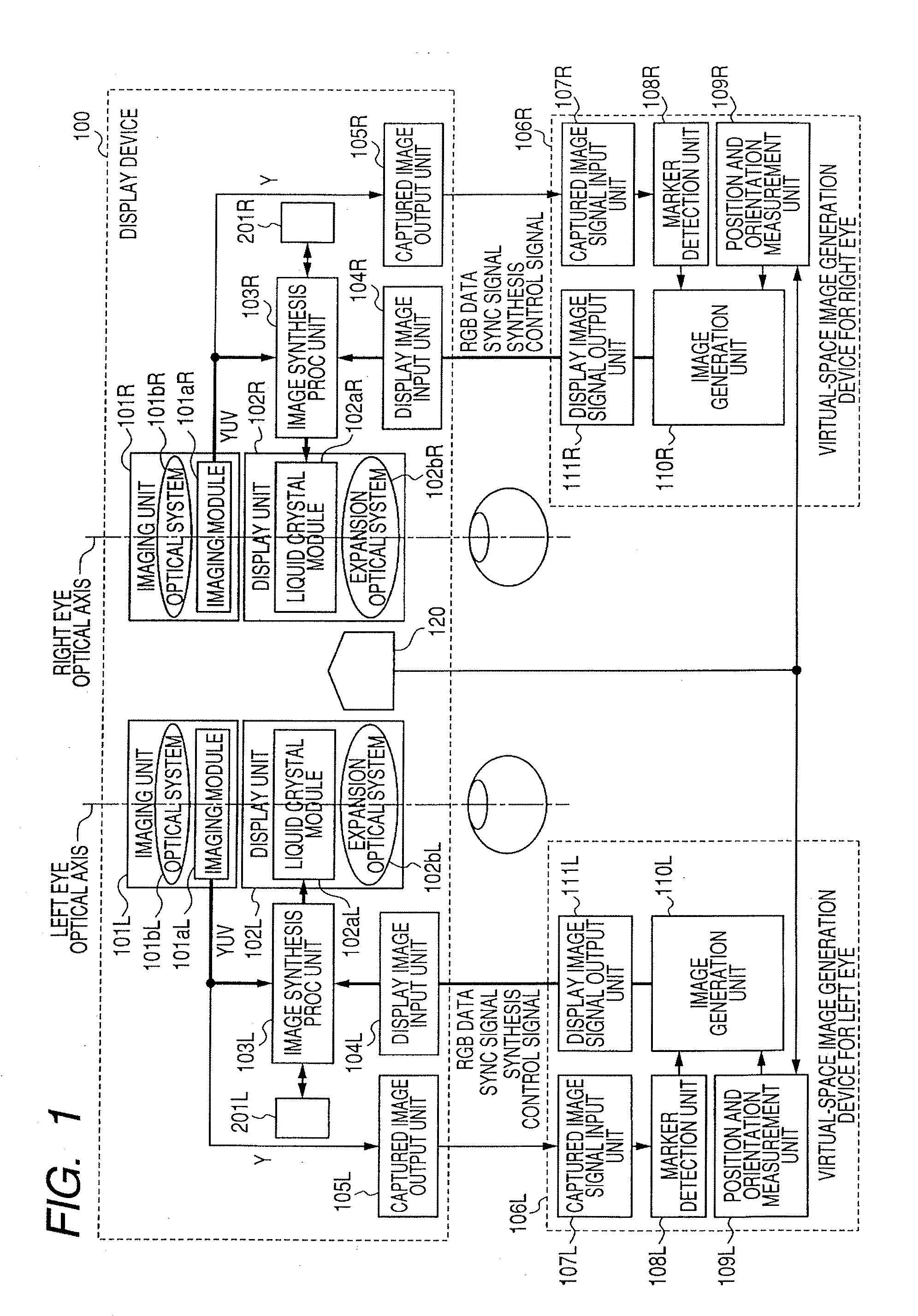
[0029]FIG. 1 a block diagram illustrating a schematic construction of the substantial part of a display system in the first exemplary embodiment that utilizes mixed reality.
[0030] In the following, the constructions of a head mounted display (or portable display) and a virtual-space image generation device will be first described, and then the operation of an image synthesis process will be described.
[0031] In FIG. 1, a head mount display device 100 has an imaging unit 101L for left eye, an imaging unit 101R for right eye, a display unit 102L for left eye, a display unit 102R for right eye, an image synthesis processing unit 103L for left eye, and an image synthesis processing unit 103R for right eye. Also, the head mount display device 100 has a captured image output unit 105L for left eye, a captured image output unit 105R for right eye, a display image input unit 104L for left eye, a display image input unit 104R for right eye, and a position and orientation sensor 120.
[0032] ...
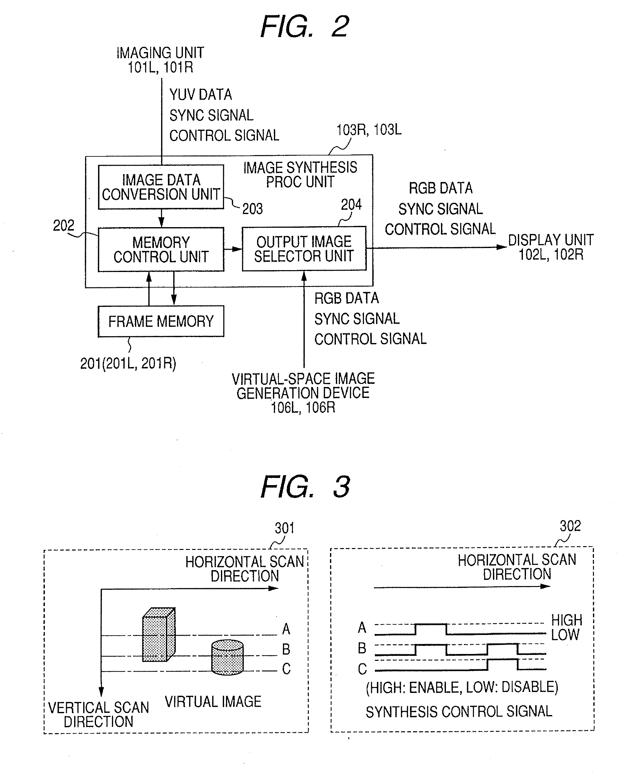
second exemplary embodiment
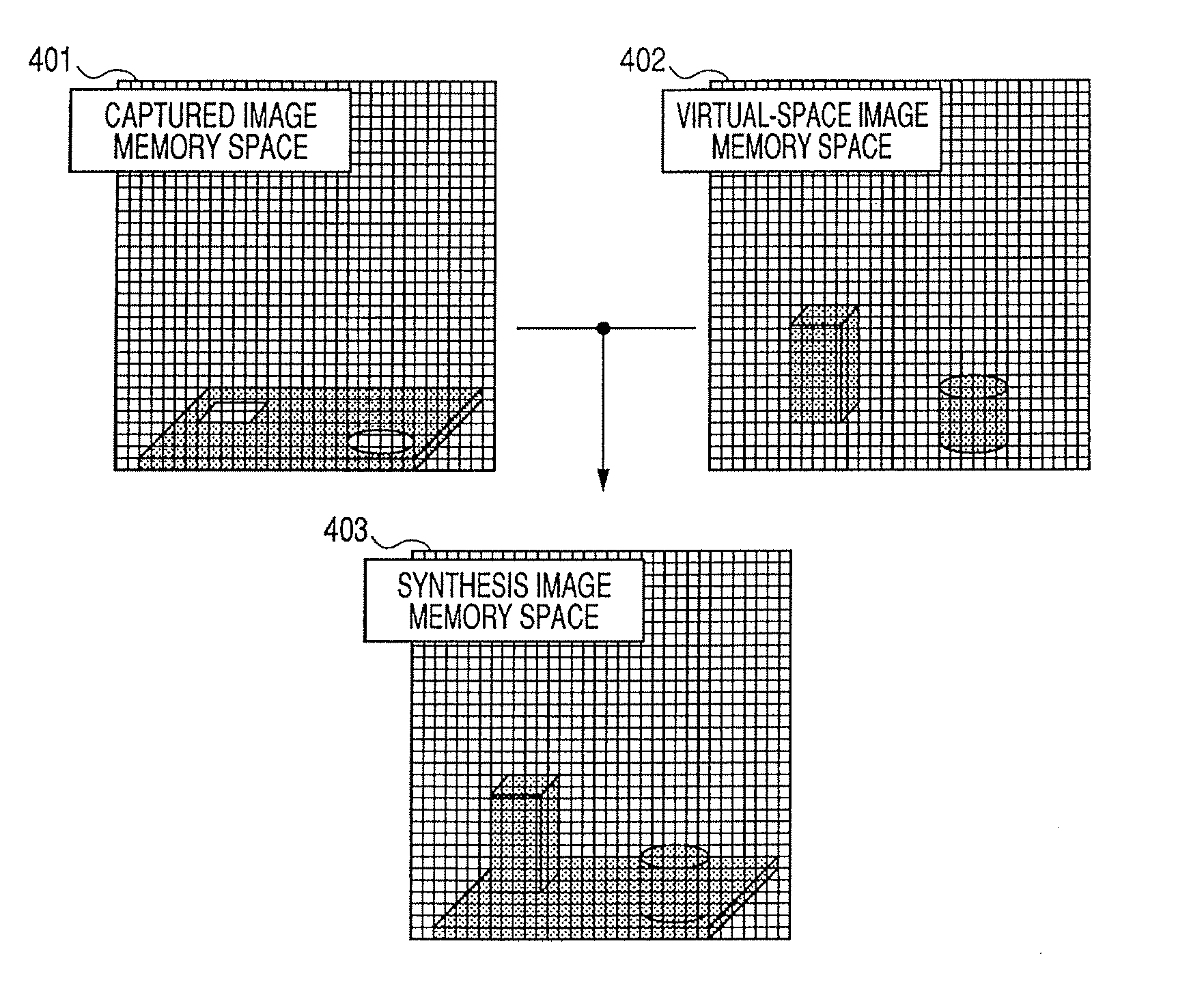
[0076]FIG. 4 is a diagram illustrating memory spaces in the second exemplary embodiment of the present invention.
[0077]FIG. 5 is a block diagram illustrating an image synthesis processing unit in the second exemplary embodiment of the present invention.
[0078] In the first exemplary embodiment, the synthesis control signal that is output from the virtual-space image generation device is used in the image synthesis process. However, the second exemplary embodiment takes another synthesis method in which data formats of coordinate addresses and color information are used to transfer synthesis image data to the head mount display device 100. In the following, only the points different from the first exemplary embodiment will be described.
[0079] More specifically, as the constituent elements of the head mount display device 100 and the virtual-space image generation devices 106L and 106R, the image synthesis processing units 103L and 103R, the display image input units 104L and 104R a...
PUM
 Abstract
Description
Claims
Application Information