Method and apparatus for clamping a riser brace assembly in nuclear reactor

a technology for nuclear reactors and riser braces, applied in the field of nuclear reactors, can solve the problems of affecting the safety of bwrs, failure of the riser brace assembly, and substantial amount of piping to be replaced or repaired

Inactive Publication Date: 2007-08-16
GENERAL ELECTRIC CO
View PDF26 Cites 28 Cited by
  • Summary
  • Abstract
  • Description
  • Claims
  • Application Information

AI Technical Summary

Problems solved by technology

However, lack of weld integrity will lead to failure of the riser brace assembly which provides support to the jet pump assembly.
Separation of the riser brace assembly 40 near this or any other weld area could adversely impact safety in BWRs.
If just one jet pump assembly is damaged, a substantial amount of piping must either be replaced or repaired.
Since weld repairs in the area of the downcomer annulus 28 are typically not practical due to inaccessibility, and the potential for excessive radiation exposure to personnel is real, a need exists for a method and apparatus of securely clamping the riser braces to the jet pump assembly.

Method used


Image

  • Method and apparatus for clamping a riser brace assembly in nuclear reactor
  • Method and apparatus for clamping a riser brace assembly in nuclear reactor
  • Method and apparatus for clamping a riser brace assembly in nuclear reactor

Examples


Embodiment Construction

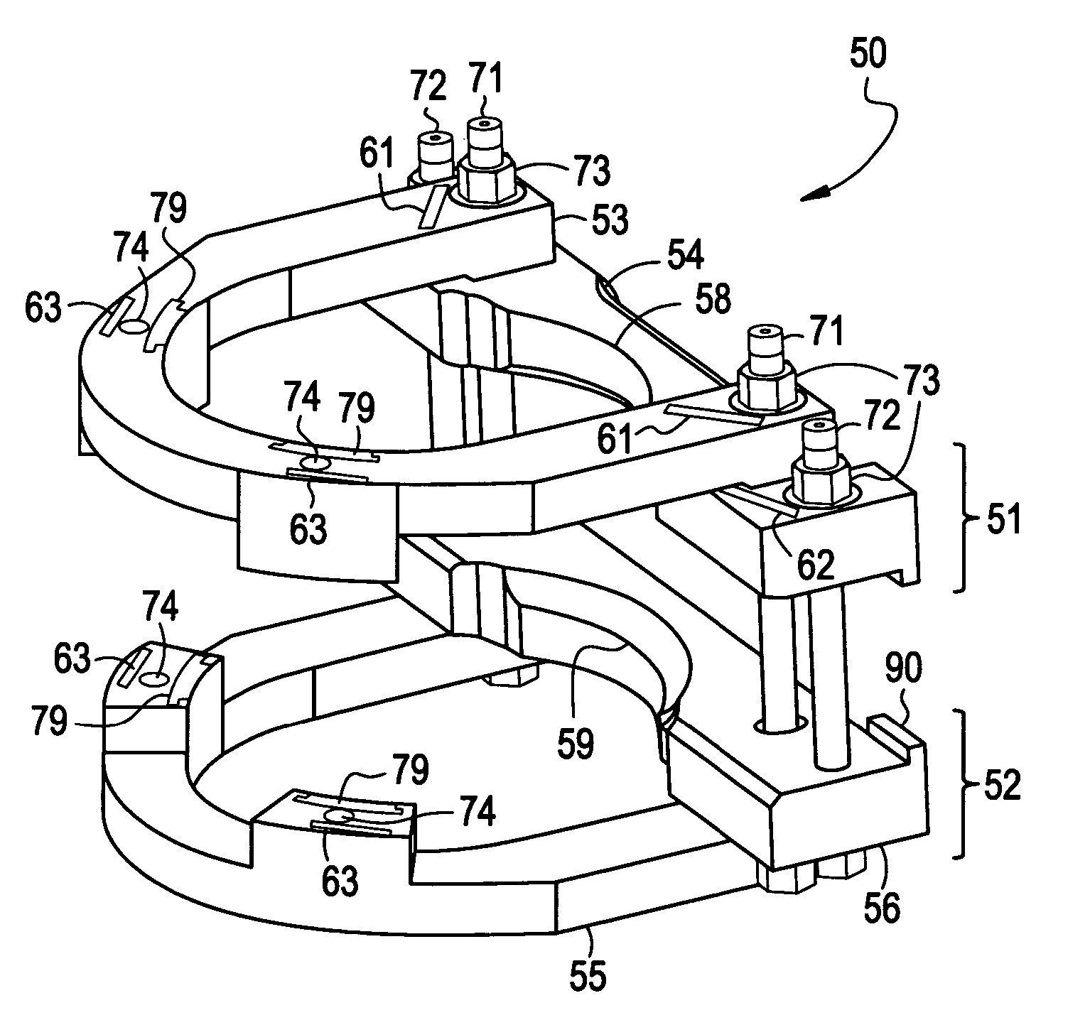
[0034] A riser brace assembly in accordance with the invention is designed to structurally replace weld(s) attached between a riser brace support and a riser pipe. In general, the installation involves electric discharge machining (EDM) the riser brace support to install the riser brace clamp assembly, assembling the hardware in the reactor, adjusting wedges to secure proper interface of the clamp assembly to the riser pipe, and preloading and locking a plurality of mechanical fasteners to secure the riser brace assembly in place.

[0035] In order for the riser brace clamp assembly to interface with the riser pipe, adjustable wedges are radially moved so that the upper and lower clamps clamp tightly on the riser pipe. These wedges may be advanced by rotation of mechanical fasteners, for example, but not limited to jack bolts. Additionally, latches are provided to lock the mechanical fasteners, and thus secure the fasteners and wedges in the desired position.

[0036]FIG. 4 is an isomet...


PUM


Abstract

An apparatus and method are provided which are designed to structurally replace welds that attach a riser brace assembly to a jet pump riser pipe. The riser brace assembly may include an upper clamp assembly, a lower clamp assembly, and a plurality of mechanical fasteners to provide clamping forces to the upper clamp assembly and the lower clamp assembly. The upper clamp assembly and the lower clamp assembly sandwich a riser brace support, wherein the riser brace support is provided with at least one through-hole to accommodate the plurality of mechanical fasteners.

Description

BACKGROUND OF THE INVENTION [0001] 1. Field of the Invention [0002] This invention relates generally to nuclear reactors and, more particularly, to a method and apparatus for clamping a riser brace assembly to a jet pump assembly of a boiling water reactor. [0003] 2. Description of Related Art [0004] A reactor pressure vessel (RPV) of a boiling water reactor (BWR) typically has a generally cylindrical shape and is closed at both ends, e.g., by a bottom head and a removable top head. A top guide typically is spaced above a core plate within the RPV. A core shroud, or shroud, typically surrounds the core and is supported by a shroud support structure. Particularly, the shroud has a generally cylindrical shape and surrounds both the core plate and the top guide. There is a space or annulus located between the cylindrical reactor pressure vessel and the cylindrically-shaped shroud. [0005]FIG. 1 is a schematic, partial cross sectional view, with parts cut away, of a reactor pressure vess...

Claims


Application Information

Patent Timeline
Patent Type & Authority Applications(United States)
IPC IPC(8): G21C19/00
CPCG21C13/02G21Y2002/206Y10T403/7067G21Y2004/301Y02E30/40G21Y2002/303Y02E30/30
Inventor JENSEN, GRANT C.
Owner GENERAL ELECTRIC CO
Why Eureka
Try Eureka