Fiber-to-the-home (FTTH) optical receiver with distributed gain control

a technology of optical receiver and distributed gain control, which is applied in the direction of gain control, transmission monitoring, multiplex communication, etc., can solve the problems of maintaining gain control, powering and power consumption, installation, and simplicity requirements of equipmen

Inactive Publication Date: 2007-08-16
CISCO TECH INC
View PDF9 Cites 5 Cited by
  • Summary
  • Abstract
  • Description
  • Claims
  • Application Information

AI Technical Summary

Problems solved by technology

Conversely, some of the disadvantages with an optical fiber system are maintaining gain control, powering and power consumption, installation, and simplicity requirements with the equipment, such as optical receivers.

Method used


Image

  • Fiber-to-the-home (FTTH) optical receiver with distributed gain control
  • Fiber-to-the-home (FTTH) optical receiver with distributed gain control
  • Fiber-to-the-home (FTTH) optical receiver with distributed gain control

Examples


first embodiment

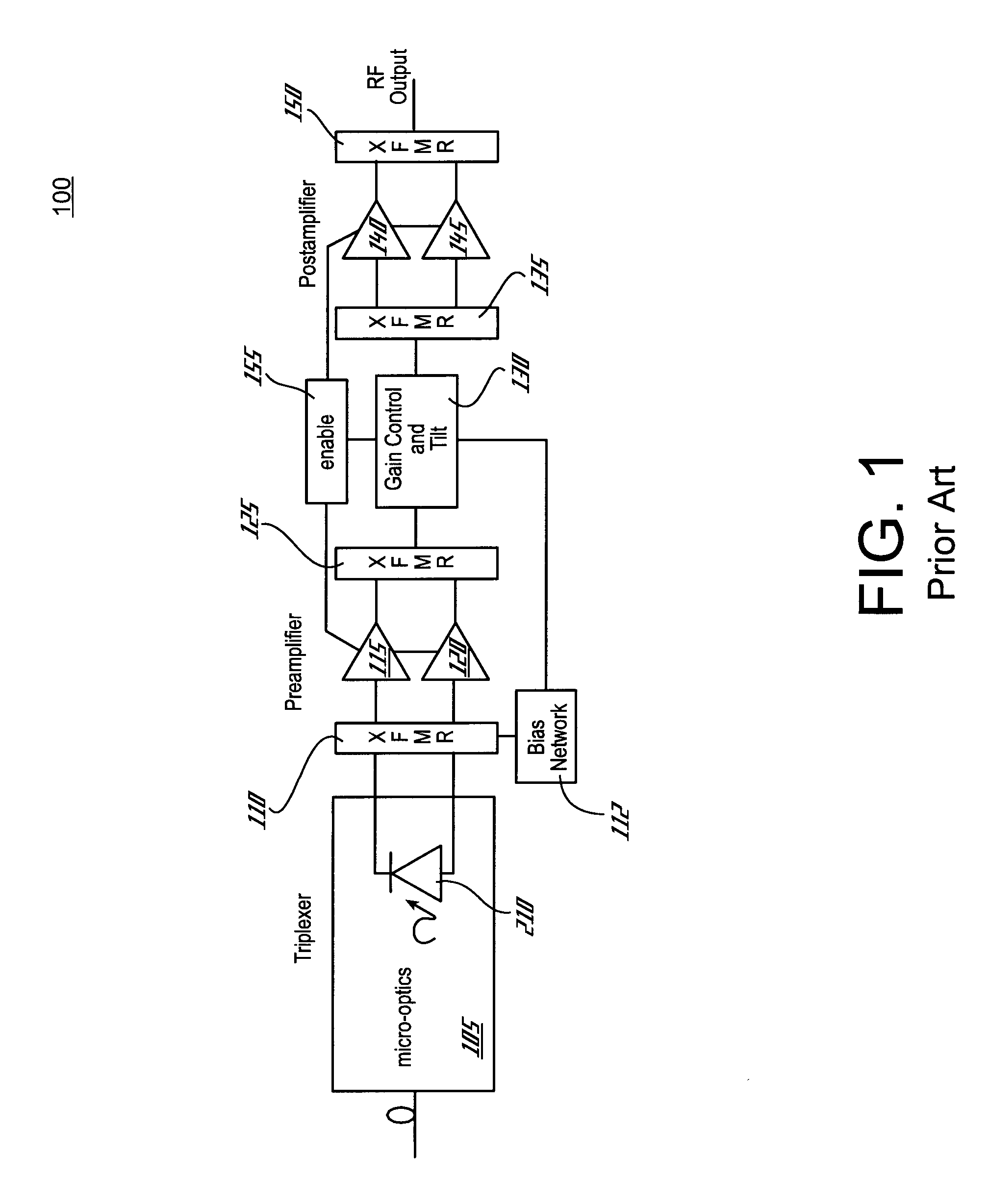
[0018]FIG. 3 is an optical receiver in accordance with the present invention that is suitable for use in an FTTH system. The optical receiver 300 in accordance with the present invention utilizes several gain stages as opposed to the conventional optical receiver 100 of FIG. 1. More specifically, in accordance with the present invention, the gain stages 320, 335, 350, 360 are distributed throughout the optical receiver 300 rather than just implementing a preamplifier and a postamplifier stage as shown in FIG. 1. In a conventional optical receiver 100, a higher power gain stage is required to maintain the linearity specifications of the RF output that is required due to the fluctuating input optical level in an FTTH system. Conversely, in accordance with the present invention noise performance is optimized and RF signal levels are prevented from increasing beyond the gain stages linear region, thus allowing for smaller, lower power consumption gain stages. It will be appreciated that...

second embodiment

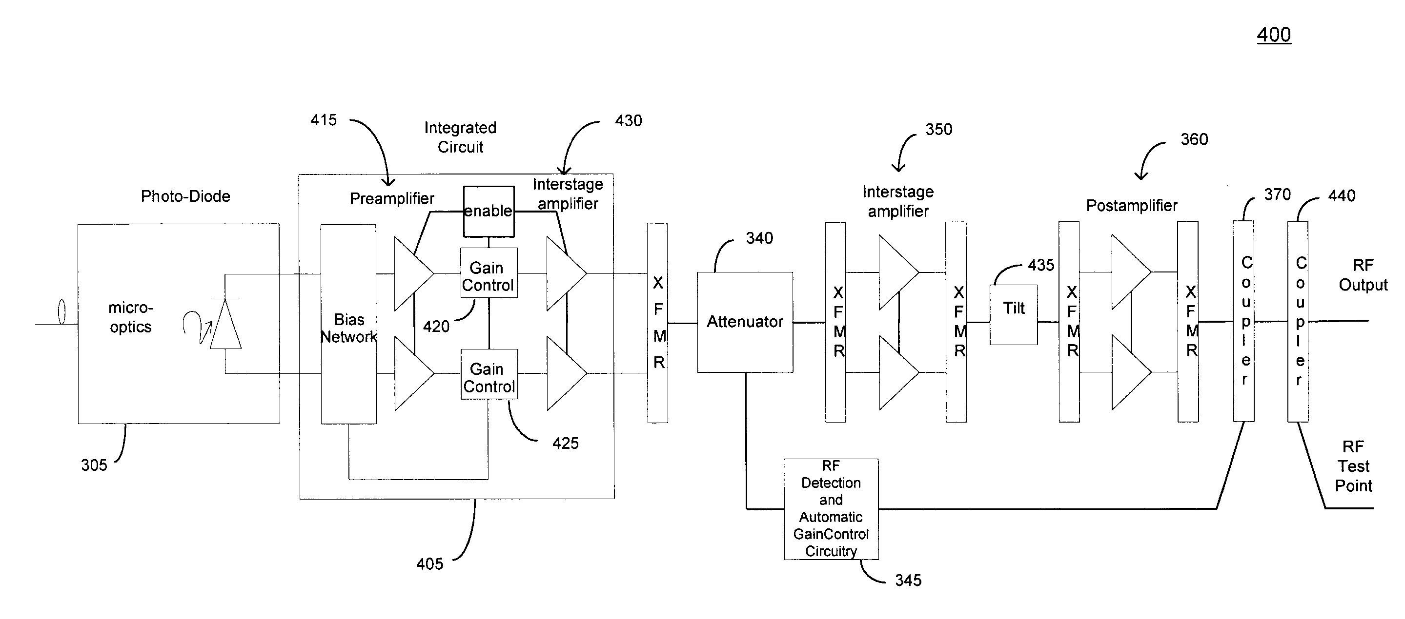
[0024]FIG. 4 is an optical receiver in accordance with the present invention. An integrated circuit 405 incorporates a preamplifier stage 415 and a first interstage amplifier 430 into one package. It will be appreciated that the integrated circuit 405 can also be coupled to the photodiode 305 either by co-locating the two circuits in one package or using the same substrate for both optics and RF electronics. The optical receiver 400 can then be mounted within an enclosure on an outside wall of a home or business. Included in the integrated circuit 405 may also be a bias network 410 and remote enabling. Gain control circuits 420, 425 are coupled between the preamplifier stage 415 and the interstage amplifier 430.

[0025] The optical receiver 400 also comprises an attenuator 340 and RF detection and automatic gain control circuitry 345. A tilt network 435 is then coupled between the second interstage amplifier 350 and the postamplifier stage 360 to ensure that the RF output is provided ...


PUM


Abstract

A fiber-to-the-home (FTTH) system transmits forward and reverse optical signals, such as video, voice, and data signals, via optical fiber, and includes a plurality of home network units. The home network units include an optical receiver for receiving at least one of the video, voice, and data signals. Included is a plurality of gain stages that are distributed throughout the optical receiver. The gain stages include a preamplifier stage, two interstage amplifiers, and a postamplifier stage. Two gain control circuits automatically adjust the gain of the video signal based upon the input power level to the FTTH optical receiver. Additionally, a tilt network performs level compensation for externally located coaxial cable. A signal is then provided to a device located within a home via the coaxial cable at the proper RF level having low noise signals.

Description

FIELD OF THE INVENTION [0001] The present invention relates to fiber-to-the-home (FTTH) optical transmission systems and more particularly to an FTTH optical receiver used in such system having distributed gain control for receiving and processing video, voice, and data optical signals while maintaining optimum performance. BACKGROUND OF THE INVENTION [0002] In recent years there has been a great deal of interest in the transmission of video, voice, and data signals via optical fiber that is pulled to the home, i.e., fiber-to-the-home (FTTH) systems. Traditionally, cable operators have provided video and data signals over a hybrid fiber / coaxial cable (HFC) system. In an FTTH system, optical signals are sent via optical fiber for transmission over longer distances. The optical signals are then converted to radio frequency (RF) signals for transmission over coaxial cable just before entering the home. In contrast, telephone operators have traditionally provided voice and data signals ...

Claims


Application Information

Patent Timeline
Patent Type & Authority Applications(United States)
IPC IPC(8): H04B10/06H04B10/43
CPCH04B10/6931H03G3/3084
Inventor RIGGSBY, ROBERT R.
Owner CISCO TECH INC
Why Eureka
Try Eureka