FTTH optical receiver

A technology of optical receivers and optical receiving units, applied in electromagnetic receivers, electromagnetic wave transmission systems, electrical components, etc., can solve problems such as inability to upgrade and replace, and achieve the effects of improving measurement accuracy, improving measurement efficiency, and facilitating adjustment

Inactive Publication Date: 2019-11-22
王耀宁
View PDF1 Cites 0 Cited by
  • Summary
  • Abstract
  • Description
  • Claims
  • Application Information

AI Technical Summary

Problems solved by technology

However, in this technical solution, the optical receiver and th

Method used


Image

  • FTTH optical receiver
  • FTTH optical receiver
  • FTTH optical receiver

Examples


Embodiment Construction

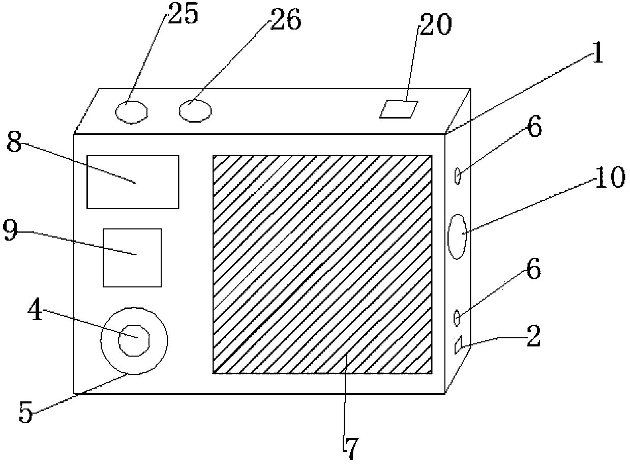
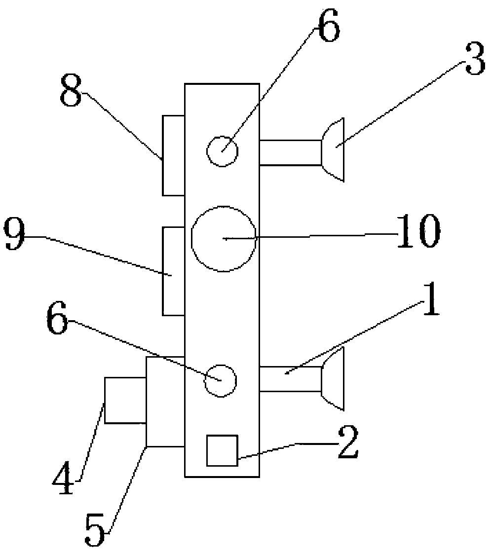
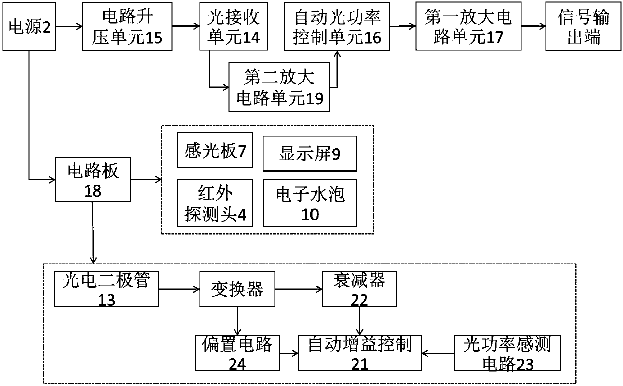
[0038] An FTTH optical receiver, including a receiver body 1, a power supply 2, a suction cup 3, an infrared detection head 4, a universal wheel 5, an adjustment knob 6, a built-in photodiode 13, a light receiving unit 14, a circuit boosting unit 15, an automatic The optical power control unit 16 and the first amplifying circuit unit 17; the present invention can be easily installed and disassembled through the suction cup 3, thereby changing its installation position conveniently, making the use process more convenient and faster;

[0039] The photodiode 13 receives an input optical signal and converts the optical signal into an RF signal. The photodiode can be a separate device if an external wavelength division multiplexing (WDM) component is used. Additionally, the photodiode 13 shown may also be a duplexer or triplexer module including WDM components. Furthermore, the photodiode 13 can be biased in various ways - such as integrated with a receiver integrated circuit.

...


PUM


Abstract

The invention relates to an FTTH optical receiver. The FTTH optical receiver comprises a receiver body, a power supply, a sucker, an infrared detection head, universal wheels, an adjusting knob, a photodiode, an optical receiving unit, a circuit boosting unit, an automatic optical power control unit and a first amplifying circuit unit, wherein the power supply, the circuit boosting unit and the light receiving unit are electrically connected in sequence; the optical receiving unit, the automatic optical power control unit and the first amplifying circuit unit are electrically connected in sequence, wherein a photosensitive plate is arranged on the receiving surface of the receiver body, and a fluorescent plate, a display screen and an electronic bubble are arranged on the receiver body onthe upper side and the lower side of the photosensitive plate. The FTTH optical receiver has the advantages that the FTTH optical receiver has the photosensitive plate and an infrared detection head,integrates the functions of distance measurement, speed measurement and temperature measurement, and can meet different measurement requirements; and the position coordinates of the laser received onthe photosensitive plate can be visually displayed through the display screen, the incident angle of the laser is convenient to adjust, and the measurement accuracy is improved.

Description

technical field [0001] The invention relates to an FTTH optical receiver. Background technique [0002] At present, in engineering measurement, because the power of the laser is too high, it will cause damage to human eyes and other organs, so the power of the laser is limited, and its brightness is also limited. The loss of the laser is large when it is far away, so that the surveyor cannot accurately judge the position of the laser with the naked eye. In order to solve this problem, a laser receiver is usually installed on the target. However, the laser receiver can only match the laser equipment with the corresponding function for operation, and the signal it receives is also single, which cannot meet the needs of use; moreover, it is difficult to install, and the position is not easy to adjust after installation; the existing laser receiver can To determine whether it is level, but it is not convenient to adjust the level of the laser receiver, which is extremely inconv...

Claims


Application Information

Patent Timeline
IPC IPC(8): H04B10/67H04B10/69
CPCH04B10/67H04B10/672H04B10/673H04B10/674H04B10/69H04B10/6911H04B10/6931H04B10/697
Inventor 王耀宁
Owner 王耀宁
Why Eureka
Try Eureka