
Drive belt

a technology of driving belts and belt loops, which is applied in the direction of driving belts, v-belts, non-woven fabrics, etc., can solve problems such as strength loss, and achieve the effects of improving heat resistance, good wear resistance, and long service li

Active Publication Date: 2007-08-16
CONTITECH ANTRIEBSSYST
View PDF5 Cites 5 Cited by
  • Summary
  • Abstract
  • Description
  • Claims
  • Application Information

AI Technical Summary

Benefits of technology

The invention provides drive belts that can withstand high temperatures and have a longer service life while maintaining good wear resistance.

Problems solved by technology

The technical problem addressed in this patent is the need for a surface coating that can protect drive belts from wear and friction while operating in high temperature ranges. The existing coating, called XYLAN®, has been shown to improve wear protection and friction performance, but can fail prematurely due to tooth shearing.

Method used


Image

  • Drive belt
  • Drive belt

Examples


Embodiment Construction

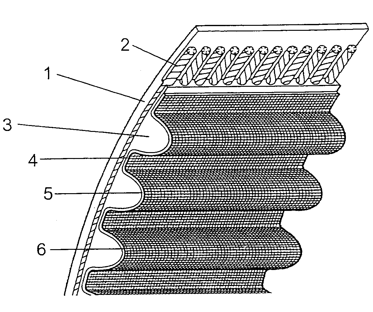
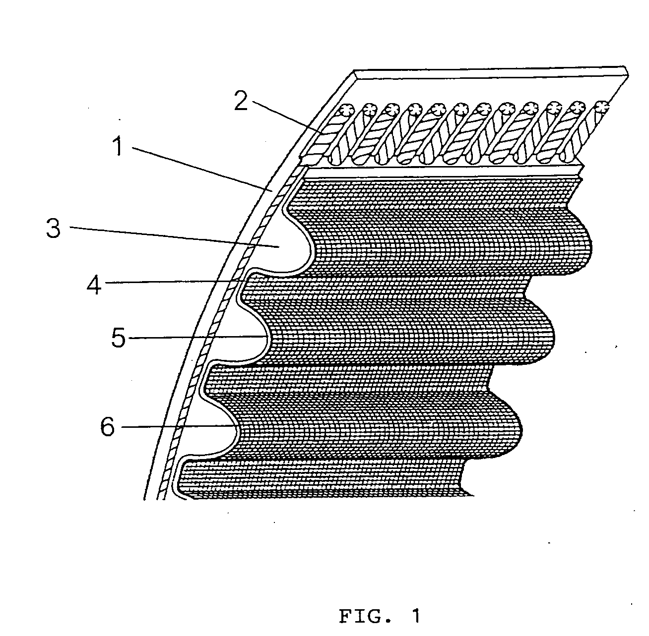
[0025]In FIG. 1, a drive belt according to the invention is shown schematically in the form of a toothed belt. The toothed belt has an elastomer cover layer 1, a tension carrier layer 2 of parallel running reinforcement cords and belt teeth 3 of elastomer material having teeth lands 4 lying therebetween. The toothed side of the belt, that is, the belt teeth 3 and the teeth lands 4 are provided with surface protection in the form of fabric 5. The outer side of the fabric surface protection 5 has a surface coating in the form of layer 6.

[0026]Three toothed belts were produced based on an HNBR rubber body and teeth, a tension carrier layer of glass cords in the body and a -6,6-polyamide stretch fabric on the teeth. The tooth fabric was, in all cases, coated with an RFL dip on the basis of CSM. Then, the fabric was dipped with an adhesive agent, a so-called overcoat, and was coated on the rubber side with a paste of HNBR rubber mixture in organic solvent. However, treatment of the oppos...


PUM

PropertyMeasurementUnit
Percent by massaaaaaaaaaa

Abstract

The invention is directed to a drive belt of rubber or rubber-like plastic having a surface protection (5) which includes polyamide-containing textile reinforcement and/or polyester-containing textile reinforcement. On the outer side, a surface coating (6) of a friction-reducing material in a matrix of at least one elastic addition polymer is provided. For improved heat resistance with good protection against wear, the elastic addition polymer has at least 2% by weight based on the polymer of structural components —O—CxRy—O— with x=1-3 and y=0-6. The R in a structural component can be the same or can be different and is selected from hydrogen and/or carbon-containing groups.

Description


Claims


Application Information

Patent Timeline
Owner CONTITECH ANTRIEBSSYST
Learn More