Shock absorbing device for shoe sole in rear foot part

a technology of shock absorption device and shoe sole, which is applied in the direction of shoes, top-pieces, heels, etc., can solve the problems of difficult deformation of the foot part of the shoe sole, large impact load on the lateral side of the heel, and no document discloses a point, etc., and achieves the effect of easy abduction or abduction of the foo

Inactive Publication Date: 2007-08-23
ASICS CORP
View PDF26 Cites 96 Cited by
  • Summary
  • Abstract
  • Description
  • Claims
  • Application Information

AI Technical Summary

Benefits of technology

[0063] If the deformation elements are easy to compress in the medial and lateral side portions, adduction or abduction of the foot may

Problems solved by technology

Thus, the lateral side of the heel is subjected to large impact load of landing.
In addition, in order to restrain the inclination of the foot toward the medial side, the rear foot part of the shoe sole may be difficult to deform on its medial side, thereby performing high supporting function.
However, none of these documents discloses a point of preventing the inclination of the foot toward the medial side.
And, since the deforming member is continuously provided from the medial side to the lateral side, it is difficult to adjust the difference of the degree of the deformation of the shoe sole due to the shock between the medial side and the lateral side.
Thus, the shoe soles of these documents are difficult to exhibit both the shock ab

Method used


Image

  • Shock absorbing device for shoe sole in rear foot part
  • Shock absorbing device for shoe sole in rear foot part
  • Shock absorbing device for shoe sole in rear foot part

Examples


first embodiment

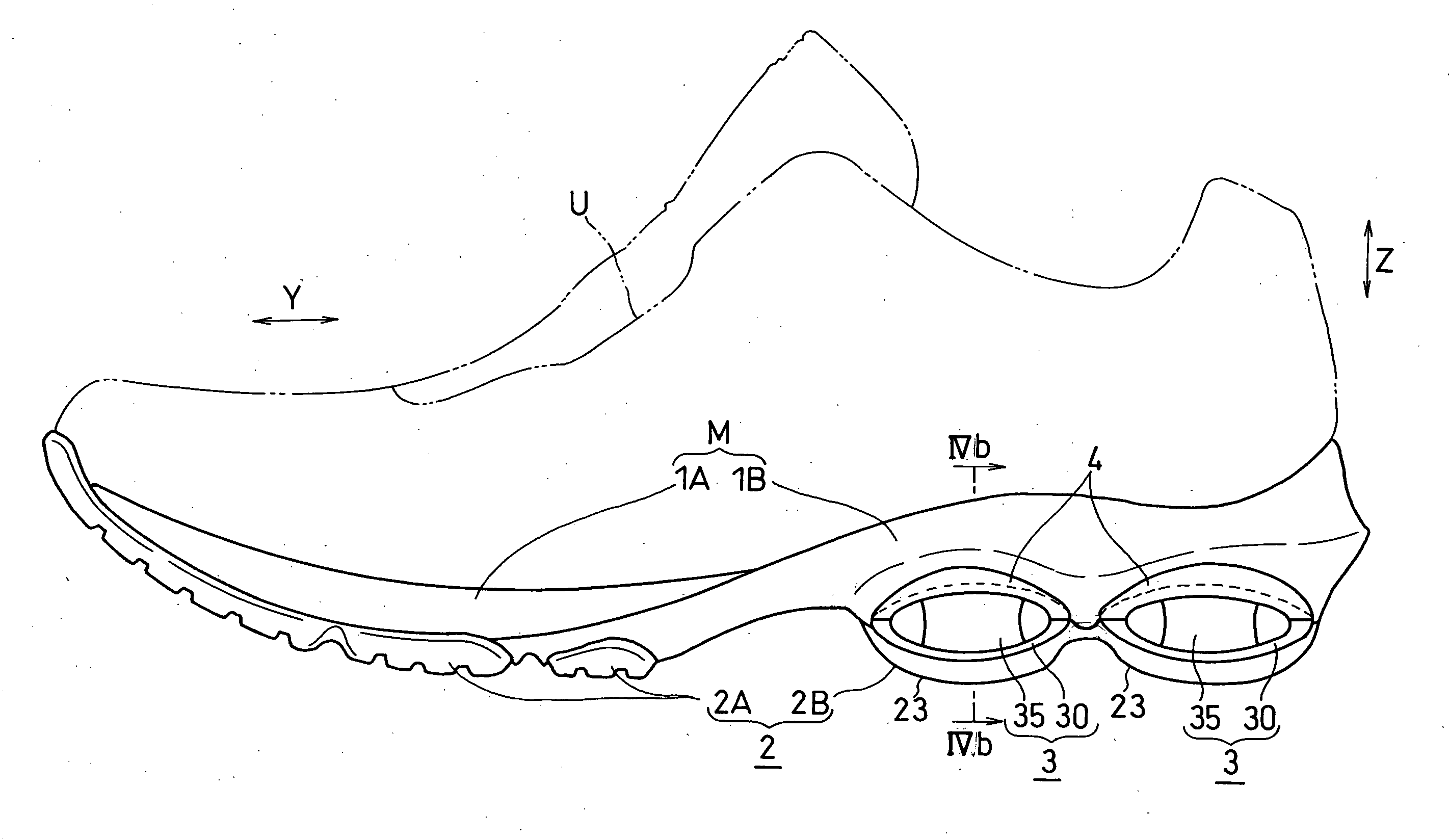
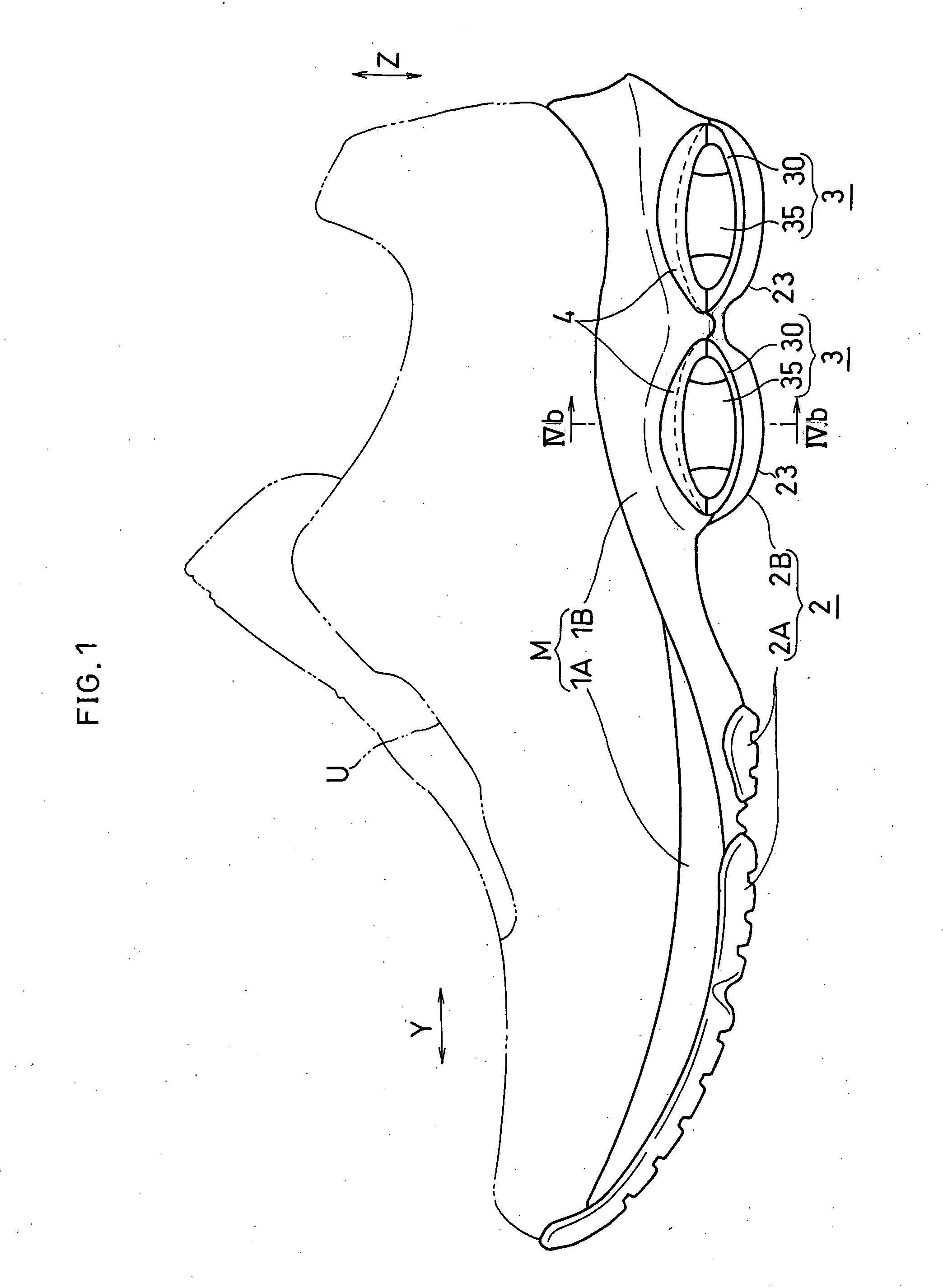
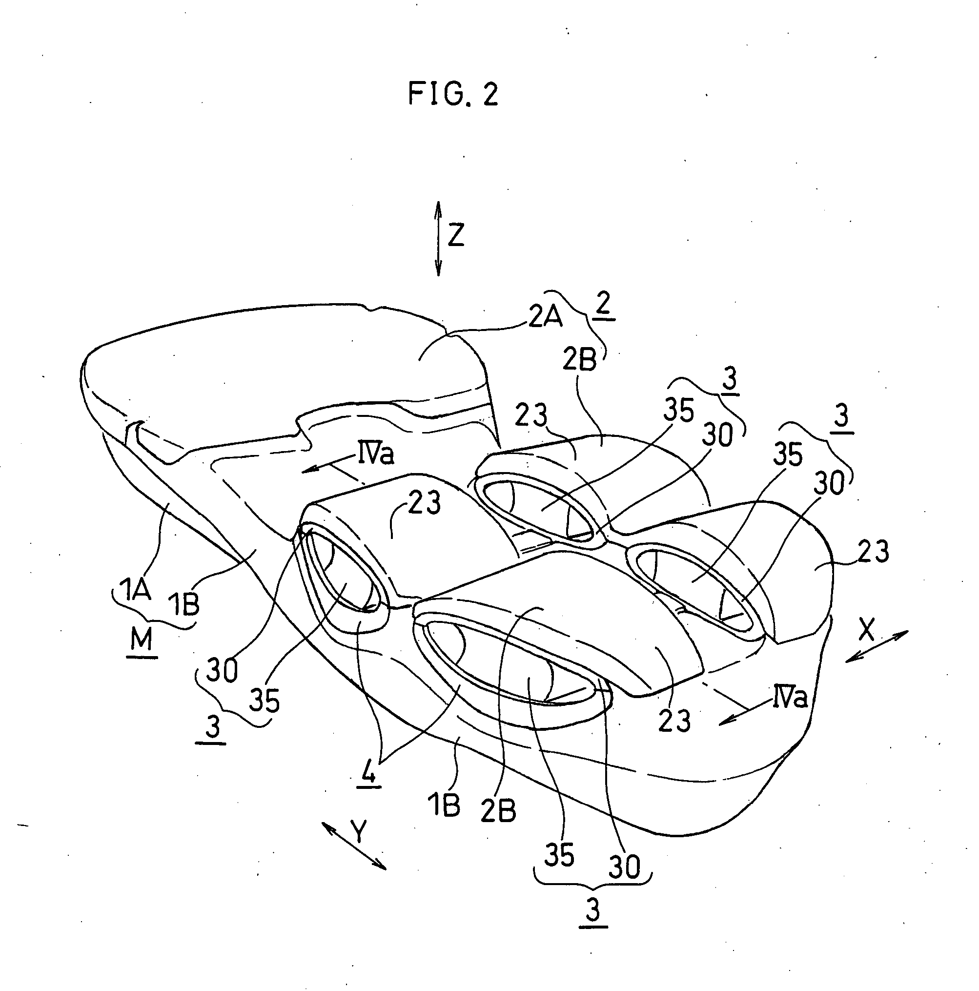
[0119] FIGS. 1 to 4 show the first embodiment of the present invention.

[0120] As shown in FIG. 1, a shoe sole of this embodiment includes a midsole (an example of a support element) M, an outer sole 2 and deformation elements 3. The midsole M is formed by vertically bonding a first midsole body 1A which is arranged in an upside and a second midsole body 1B which is arranged in a downside. The outer sole 2, a so-called shank (not shown) etc. are disposed on bottom surfaces of the midsole bodies 1A, 1B. An insole (not shown) is bonded onto the first midsole body 1A. Each midsole body 1A, 1B is, for example, formed of a material suitable for shock absorption, such as resin foam of EVA (ethylene-vinyl acetate copolymer), polyurethane or the like. Above the midsole M and the insole, an upper U that is suitable for covering the instep of the foot is disposed. The outer sole 2 that gets contact with the ground surface or the floor surface at the time of landing is formed of a material hav...

second embodiment

[0161]FIG. 5 shows the second embodiment. Note that, in the description of the following embodiments, the parts which are identical or corresponding to those of the first embodiment are designated by the same reference numerals as the first embodiment and the detailed description thereof will be omitted.

[0162] In this embodiment, as shown in FIG. 5, the deformation elements 3 is also provided on the medial and lateral sides of the fore foot part of the foot in addition to the rear foot part of the foot. This deformation element 3 consists of the tubular part 30. That is, unlike the first embodiment, there is no cushioning member within the tubular part 30, and therefore, the tubular part 30 is hollow on the inside.

[0163] In this embodiment, the connecting member for retaining the tubular part 30 is not provided, and the upper portion 32 of the tubular part 30 (lower half of the tubular part 30 in FIG. 5) is directly fit into the second curved surface 12 of the midsole M. The upper...

third embodiment

[0165] FIGS. 6 to 8 shows the third embodiment. In the figures, the arrow IN indicates the direction toward the medial side of the foot, the arrow OUT indicates the direction toward the lateral side of the foot, the arrow F indicates the direction toward the front of the foot and the arrow B indicates the direction toward the rear of the foot.

[0166] In this embodiment, as shown in FIG. 6, a plurality of generally columnar deformation elements 3 are provided. The connecting member 4 for retaining these deformation elements 3 is provided to be continuous along a side face of the rear foot part of the foot.

[0167]FIG. 7 is an exploded perspective view of the deformation elements 3, the connecting member 4 and so on in the rear foot part of the foot.

[0168] In this embodiment, as shown in FIG. 7, three deformation elements 3 are provided in the rear foot part. The upper and bottom surfaces of each deformation element 3 are formed to be flat (uncurved).

[0169] The first deformation elem...


PUM


Abstract

The present invention provides a shock absorbing device for a shoe sole in a rear foot part which can restrain the inclination of the foot toward the medial side while absorbing the shock of landing on the lateral side of the foot. A shock absorbing device for a shoe sole in a rear foot part according to the present invention, includes: a support element M; deformation elements 3 disposed below the support element, the deformation elements deforming to be compressed vertically at landing; and outer sole elements 2 contacting a ground at landing, each outer sole element being joined to a bottom surface of the respective deformation element. Both the deformation elements 3 and the outer sole elements 2 are substantially separated in a medial-lateral direction in the rear foot part to be arranged at least three regions of the rear foot part. A quotient obtained by dividing an area of a bottom surface of the support element M by an area of bottom surfaces of the outer sole elements 2 is set at about 1.3 or more in the rear foot part. A vertical compressive stiffness of the deformation element 3 disposed on the lateral side is smaller than that of the deformation element 3 disposed on the medial side.

Description

TECHNICAL FIELD [0001] The present invention relates to a shock absorbing device of a shoe sole in a rear foot part. BACKGROUND ART [0002] The cushioning function of absorbing and alleviating the shock at landing is demanded in shoe soles, in addition to the lightness in weight and the function of supporting the foot stably. [0003] Generally, during running, a foot lands on the ground from a lateral side of a heel becomes and then inclines toward a medial side. Thus, the lateral side of the heel is subjected to large impact load of landing. Therefore, a rear foot part of the shoe sole can perform high cushioning function by deforming greatly on its lateral side. In addition, in order to restrain the inclination of the foot toward the medial side, the rear foot part of the shoe sole may be difficult to deform on its medial side, thereby performing high supporting function. Thus, it is preferred that the degree of the deformation of the shoe sole due to the shock differs between the m...

Claims


Application Information

Patent Timeline
IPC IPC(8): A43B13/28A43B13/18A43B21/28
CPCA43B13/184A43B13/189A43B13/188A43B13/186A43B21/265
Inventor NISHIWAKI, TSUYOSHISENDA, SHINJI
Owner ASICS CORP
Why Eureka
Try Eureka