Liquid radioactive waste treatment system

Inactive Publication Date: 2007-08-23
KOREA ATOMIC ENERGY RES INST
View PDF10 Cites 3 Cited by
  • Summary
  • Abstract
  • Description
  • Claims
  • Application Information

AI Technical Summary

Benefits of technology

[0009] The present invention provides a liquid radioactive waste treatment system which uses solar heat, and thereby improving an energy consumption efficiency and performance efficiency.
[0010] The present invention also provides a liquid radioactive waste treatment system which may process a great amount of liquid radioactive waste, be advantageous for maintenance and repair, and be semi-permanently used, with a simple and small-sized structure.
[0011] The present invention also provides a liquid radioactive waste treatment system which increases a period of time for liquid to contact with air and solar heat, and thereby may improve an evaporation efficiency and rapidly process a great amount of liquid radioactive waste.
[0012] The present invention also provides a liquid radioactive waste treatment system which may prevent a channeling phenomenon.
[0016] Also, an inlet fan and an exhaust fan are mounted on the external wall of the housing. Air which is flowed inside of the housing from the inlet fan, passes over the evaporation plate, and is discharged to an outside of the housing via the exhaust fan after monitoring system. Such airflow improves an evaporation efficiency.
[0019] The liquid radioactive waste treatment system has a high energy consumption efficiency and may be semi-permanently used by using solar heat. Also, in the liquid radioactive waste treatment system, a period of time for contacting with the solar heat and air increases, and thereby may have a high evaporation efficiency, and may rapidly process a great amount of liquid waste. Also, a channeling phenomenon may be prevented.

Problems solved by technology

The transportation and processing of the liquid waste is more difficult than with solid waste.
However, an energy consumption efficiency and process efficiency of such method are low, which is uneconomical.
However, the evaporation fabric using fabrics is exposed to direct sunlight, and thus an evaporation fabric life is shortened, and a great amount of solid waste may be generated.
When the evaporation fabric is vertically installed, a period of time for contacting the liquid waste with air is short, and thereby causing a low evaporation efficiency.

Method used


Image

  • Liquid radioactive waste treatment system
  • Liquid radioactive waste treatment system
  • Liquid radioactive waste treatment system

Examples


Embodiment Construction

[0027] Reference will now be made in detail to embodiments of the present invention, examples of which are illustrated in the accompanying drawings, wherein like reference numerals refer to the like elements throughout. The embodiments are described below in order to explain the present invention by referring to the figures.

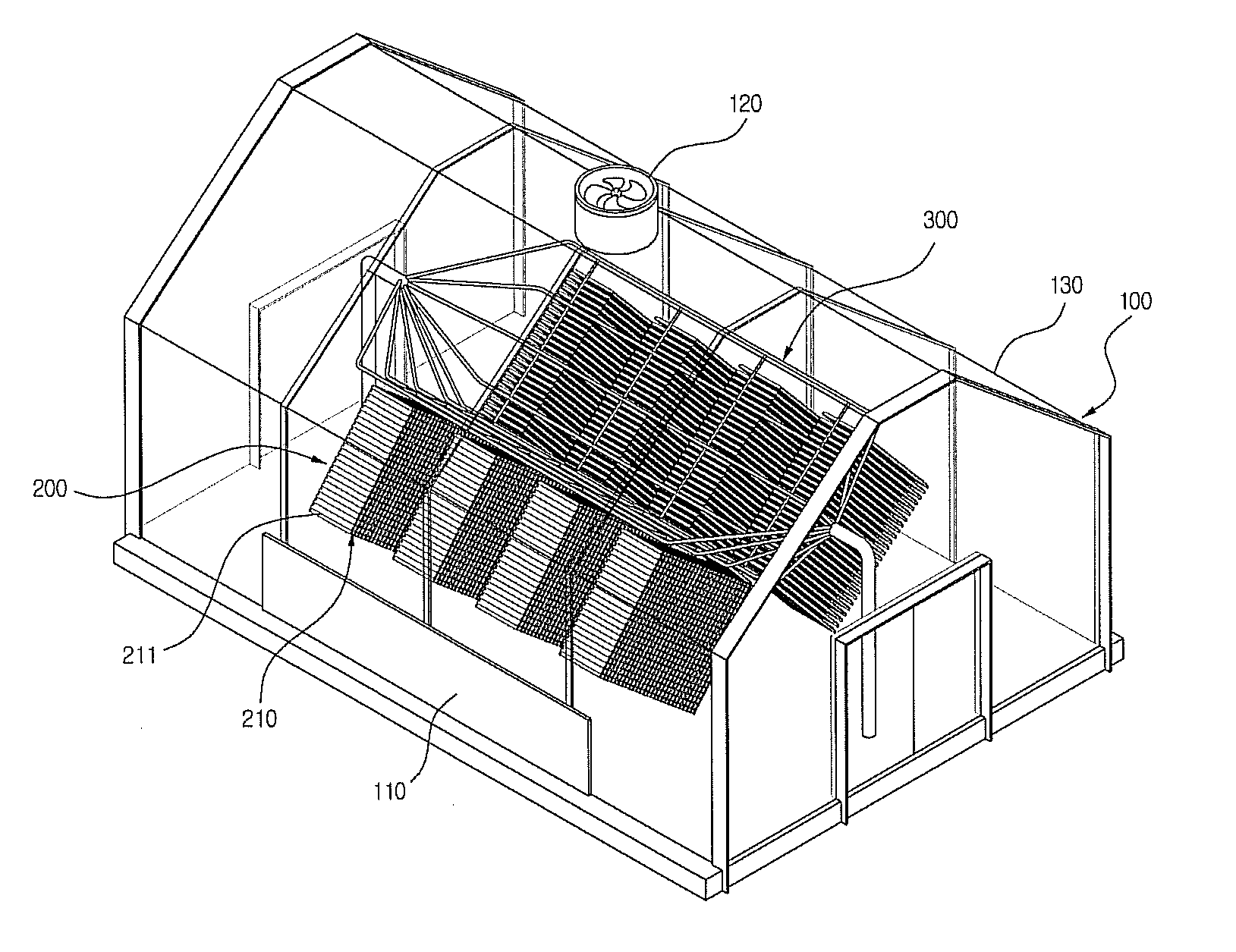
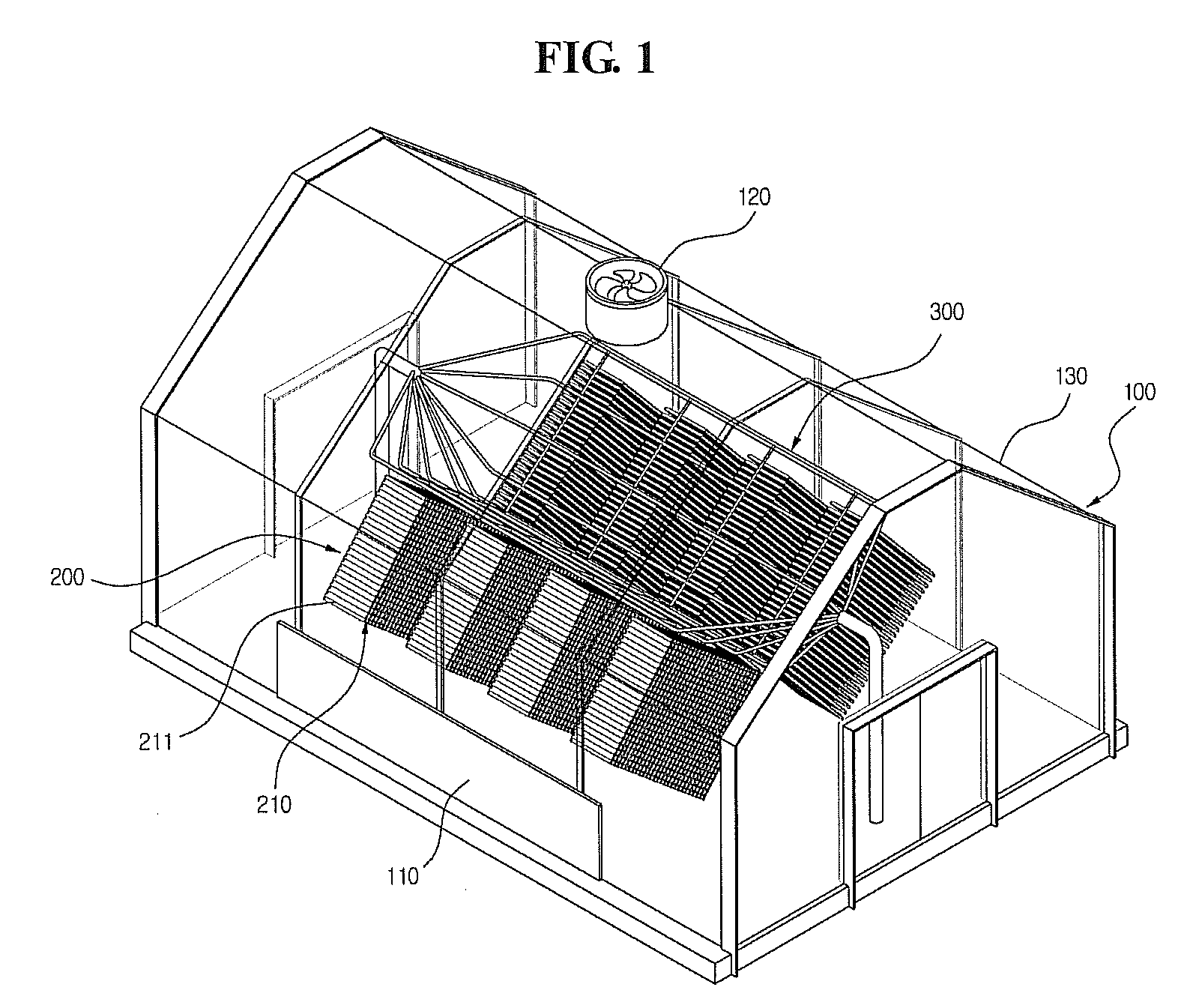
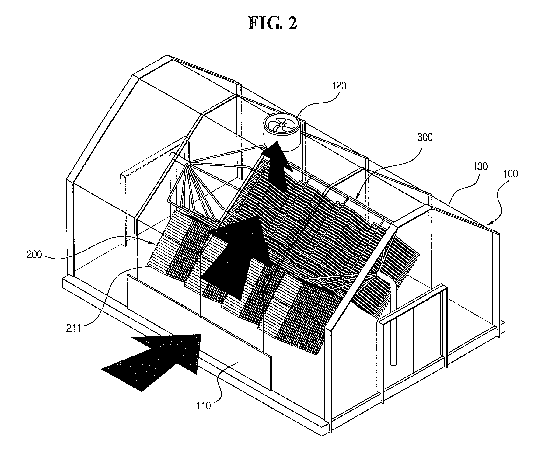
[0028]FIG. 1 is a perspective view illustrating a liquid radioactive waste treatment system according to an embodiment of the present invention. FIG. 2 is a perspective view illustrating a flow of air. FIG. 3 is a perspective view illustrating an evaporation plate.

[0029] As illustrated in FIGS. 1, 2 and 3, the liquid radioactive waste treatment system according to an embodiment of the present invention includes a housing 100, an evaporation unit 200, and a liquid waste dispersing unit 300. The housing 100 includes an external wall 130, and an interior space for the evaporation unit 200 and the liquid waste dispersing unit 300. The external wall 130 of the housi...


PUM


Abstract

The present invention relates to a liquid radioactive waste treatment system. The liquid radioactive waste treatment system includes a plurality of evaporation plates and each of the evaporation plates has an uneven surface, in a housing comprised of a glass. A liquid radioactive waste is dispersed via a liquid waste dispersing unit to the evaporation plate, and the liquid radioactive waste is evaporated using solar heat and airflow in the housing.

Description

BACKGROUND OF THE INVENTION [0001] 1. Field of the Invention [0002] The present invention relates to a liquid radioactive waste treatment system which evaporates a liquid radioactive waste in a natural environment, and more particularly, to a liquid radioactive waste treatment system in which solar heat is used, outside air is drawn in and circulated, and a liquid waste is in contact with the outside air and evaporated. [0003] 2. Description of Related Art [0004] Radioactive waste is divided into solid, liquid, and gaseous radioactive waste. [0005] Not as much research on liquid radioactive waste management has been carrying out as research on radioactive solid waste management. Liquid radioactive waste is generated by nuclear power generation or radioactive isotope use. The generated liquid waste is required to be safely processed and managed to prevent the waste from harming humans. Also, an evaporation process is required for volume reduction. [0006] As an amount of liquid waste ...

Claims


Application Information

Patent Timeline
IPC IPC(8): B01D1/14
CPCG21F9/08Y10S159/15Y10S159/12Y10S159/901Y10S159/903
Inventor KIM, TAE-KUKSHON, JONG-SIKHONG, KWONG-PYECHO, HAN-SEOK
Owner KOREA ATOMIC ENERGY RES INST
Why Eureka
Try Eureka