Monitoring formation properties

Inactive Publication Date: 2007-08-23
SHELL OIL CO
View PDF13 Cites 49 Cited by
  • Summary
  • Abstract
  • Description
  • Claims
  • Application Information

AI Technical Summary

Benefits of technology

[0009] The present inventions include a method for monitoring pressure in a formation traversed by at least one wellbore comprising providing a tubular element having an outside surface, attaching a perforating gun oriented in such a way that when fired, the perforating gun does not damage the tubular element, connecting a sensor to the perforating gun in close

Problems solved by technology

The FPT method works well in permeable formations; however, it is limited to one data point for pressure at a specified time.
Obtaining multiple data points is desirable because it is difficult to determine whether a pressure measurement reflects the virgin formation pressure or pressure after depletion.
In tighter, less permeable formations, the traditional FPT method has limits because it takes a long time to build up to the formation pressure.
In addition, the method is less accurate in formations prone to a phenomenon known as supercharging.
In supercharged reservoirs, the mudcake fails to adequately hold the drilling fluid in the wellbore, causing drilling fluid to penetrate the formation and create a high-pressure or “super-charged” zone.
Using the FPT method under these conditions may require extrapolation or yield an inaccurate data point for pressure that is between the mud pressure and the

Method used


Image

  • Monitoring formation properties
  • Monitoring formation properties
  • Monitoring formation properties

Examples


Embodiment Construction

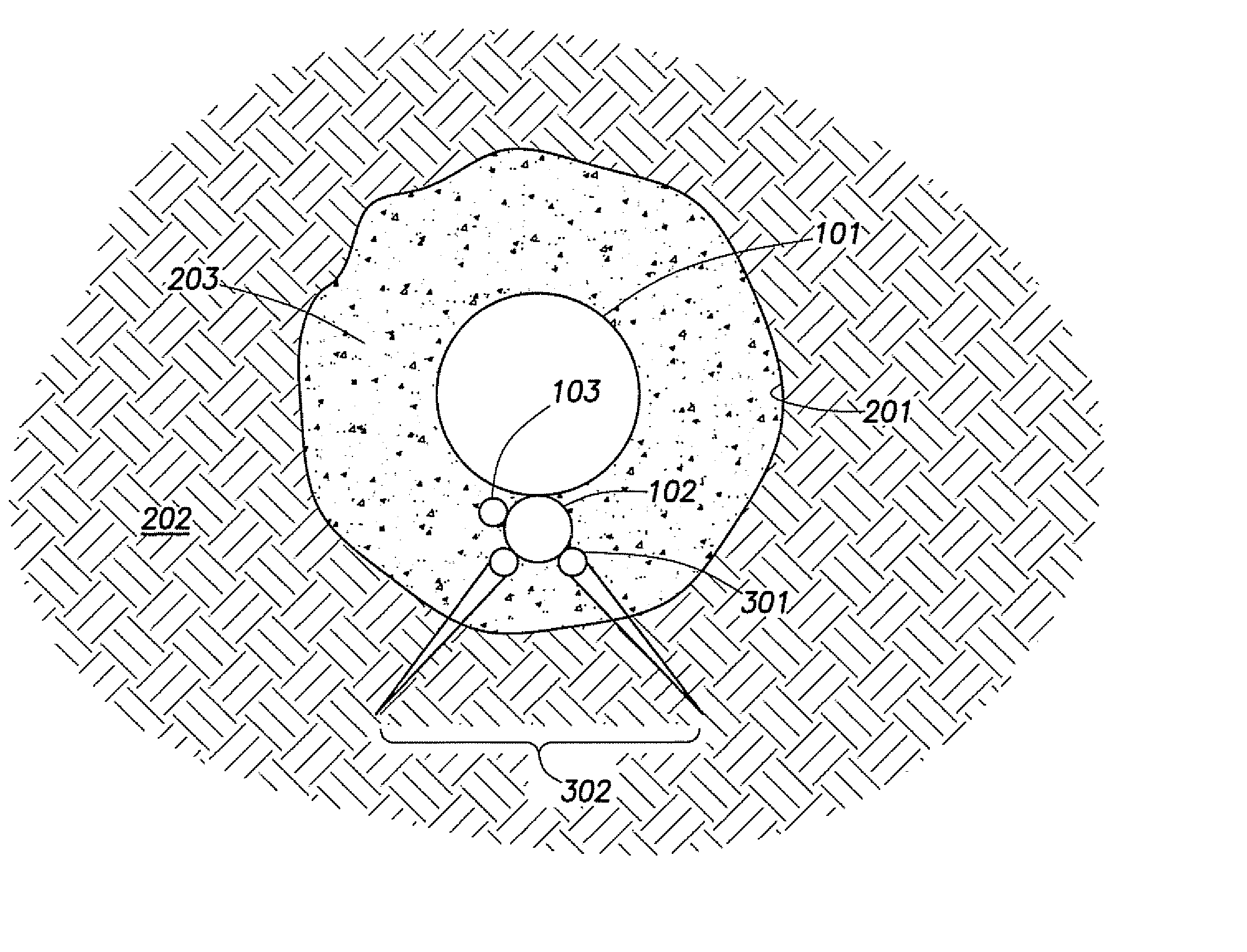
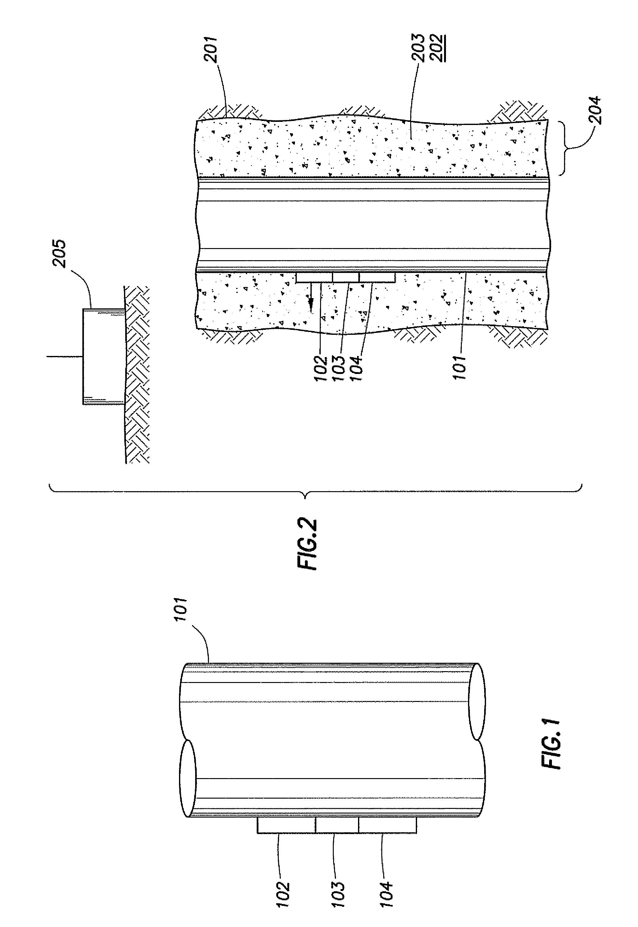
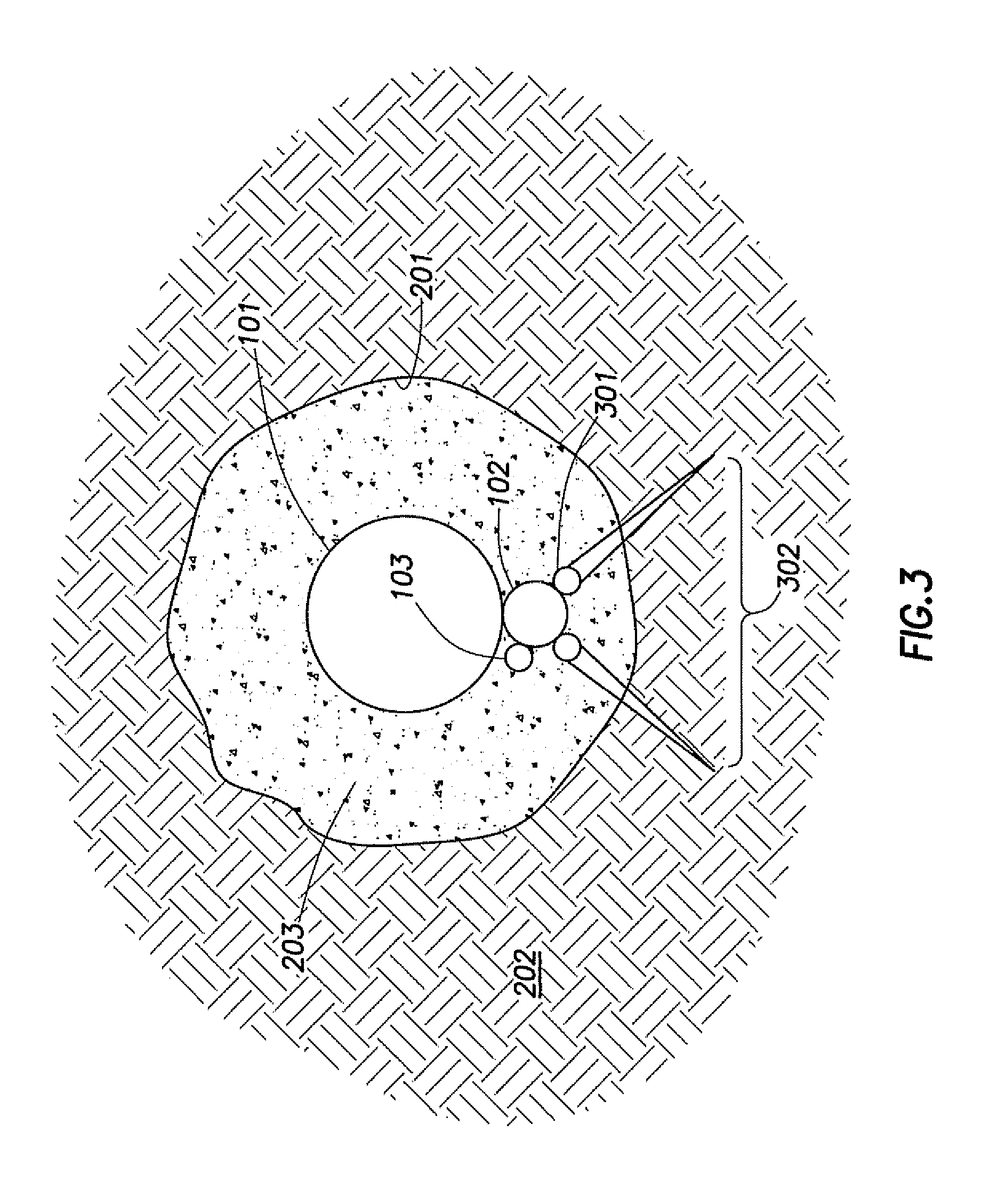
[0017]FIG. 1 shows one embodiment of an apparatus for monitoring formation properties. In this embodiment, tubular element 101 is a section of casing, liner, or other material used to maintain the integrity of the wellbore. Tubular element 101 may also be a section of tubing, cement stinger, or other device used to lower equipment into a wellbore. Perforating gun 102 and sensor 103 are mounted on the outside of tubular element 101 in close proximity to one another. Perforating gun 102 and sensor 103 may be connected either directly or via additional tubulars or hoses.

[0018] Any type of perforating gun may be used; however the direction of the perforations must point away from the casing (tubular element 101) so that when fired, the perforating gun does not damage the casing. In a wireless embodiment of the invention, perforation gun 102 may be fired by pressuring up the casing using conventional methods of wireless perforating. In an alternative embodiment, a wire may be attached t...


PUM


Abstract

A method for monitoring pressure in a formation traversed by at least one wellbore comprising providing a tubular element having an outside surface, attaching a perforating gun oriented in such a way that when fired, the perforating gun does not damage the tubular element, connecting a sensor to the perforating gun in close proximity to the perforating gun wherein the sensor is exposed to the wellbore, inserting the tubular element into the wellbore, securing the tubular element in the wellbore, firing the perforating gun to penetrate the formation, exposing the sensor to the formation pressure, and monitoring the pressure in the formation with the sensor to obtain pressure data.

Description

[0001] The present application claims the benefit of pending U.S. Provisional Patent Application Ser. No. 60 / 733,461 filed Nov. 4, 2005 the entire disclosure of which is hereby incorporated by reference.FIELD OF INVENTION [0002] The present invention relates to a method and apparatus for monitoring properties in a formation traversed by at least one wellbore. BACKGROUND [0003] In the oil and gas industry, the sampling of fluids and measuring formation pressure in the porous strata of the formation being drilled can provide valuable information about the formation and its ability to yield oil and / or gas. Formation pressure is one of the key properties that engineers, geologists, and petrophysicists use to characterize the mobility of oil and gas formations and estimate reserves. Formation pressure data can be collected at specific times throughout the life of the well or it can be monitored on a long-term basis. Ideally, operators would like to be able to obtain a real time pressure ...

Claims


Application Information

Patent Timeline
IPC IPC(8): E21B43/117E21B47/00
CPCE21B43/119E21B47/06E21B47/01
Inventor QUINT, EDWINUS
Owner SHELL OIL CO
Why Eureka
Try Eureka