Slide-out room and components used in the manufacture of the same

a technology for sliding out and components, applied in the direction of transportation and packaging, transportation items, items transportation vehicles, etc., can solve the problems of insufficient strength of the seal flange fastened to the slide-out end wall, inconvenient adjustment, and inability to seat properly. to achieve the effect of convenient adaptation

Inactive Publication Date: 2007-08-23
R N R INT
View PDF12 Cites 24 Cited by
  • Summary
  • Abstract
  • Description
  • Claims
  • Application Information

AI Technical Summary

Benefits of technology

[0006] The slide-out room embodying this invention eliminates the need for an extensive framework upon which the room is constructed. The unique configuration of the main extrusion members allows the end wall sub-frame to be assembled using key-locked miter joints, which ensure a sturdy and rigid structure upon which the slide-out room is built. The design and construction of the end wall sub-frame using the unique configuration of the main extrusion member in conjunction with a conventional angle extrusion allows the end wall sub-frame to be readily adapted for use with monocoque panels of different widths. The end wall sub-frame also eliminates the need for seal flanges fastened around the periphery of the slide-out end wall. The backs of the main extrusion members are oversized and extend peripherally beyond the side walls, ceiling and floor of the slide-out room to act as a seal flange.

Problems solved by technology

The design and construction of conventional slide-out rooms present several present practical problems in RV and other manufactured housing applications.
In addition, the conventional design and construction of slide-out rooms have been a source of sealing problems when the slide-out room is retracted into the RV interior.
If the slide-out room is not constructed to be perfectly square or is not retracted uniformly into the RV interior, the gasket on the flange also will not seat properly.
More importantly, these seal flanges fastened to the slide-out end wall are not sturdy enough to provide a proper seal over extended use.

Method used


Image

  • Slide-out room and components used in the manufacture of the same
  • Slide-out room and components used in the manufacture of the same
  • Slide-out room and components used in the manufacture of the same

Examples


Embodiment Construction

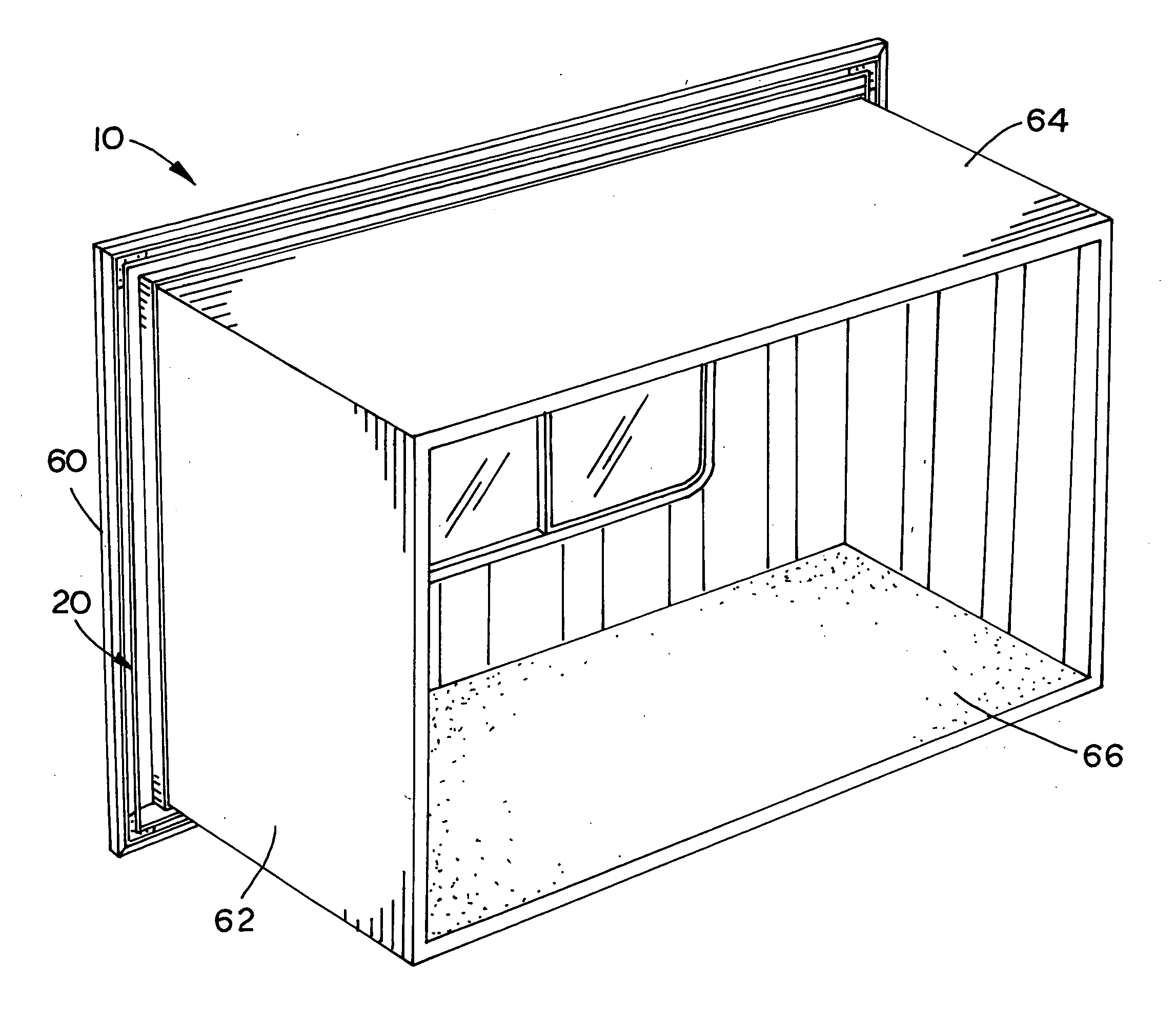
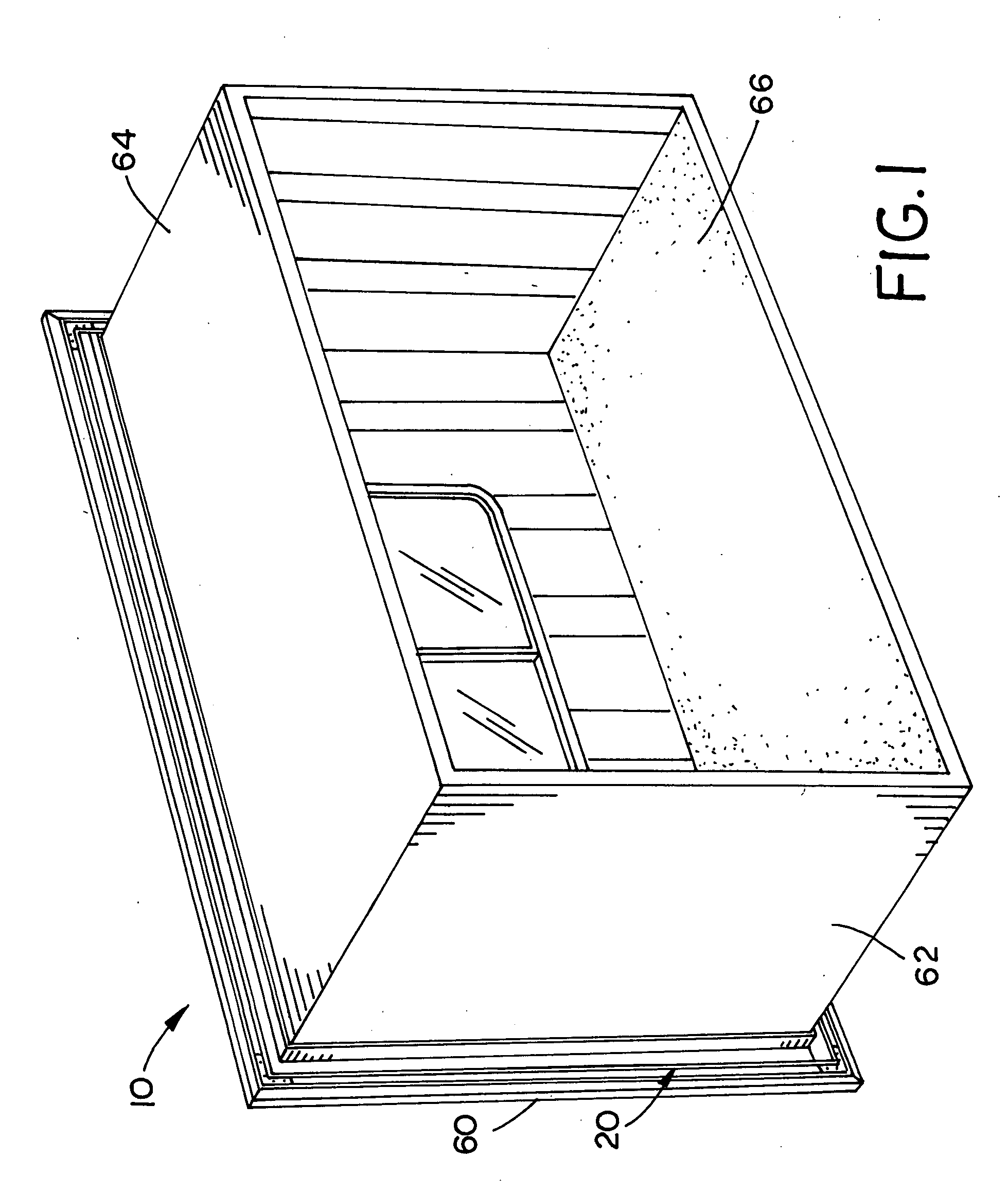
[0020] Referring now to the drawings, the slide-out room embodying the teaching of this invention is generally designated as reference numeral 10. Slide-out room 10 is constructed from monocoque laminate wall panels interconnected by an end wall sub-frame 20. Monocoque laminate wall panels are well known in the recreational vehicle industry. Monocoque wall panels are light weight and can be constructed in any desirable width, size or configuration. As best illustrated in FIG. 11, the monocoque wall panels have an internal tubular aluminum skeleton and an insulated core sandwiched between outer skins. The internal skeleton provides structural integrity to the panel. Typically, the insulation core is a polyester / styrene copolymer and the outer skins are a gel-coat, such as Filon, bonded to lauan plywood.

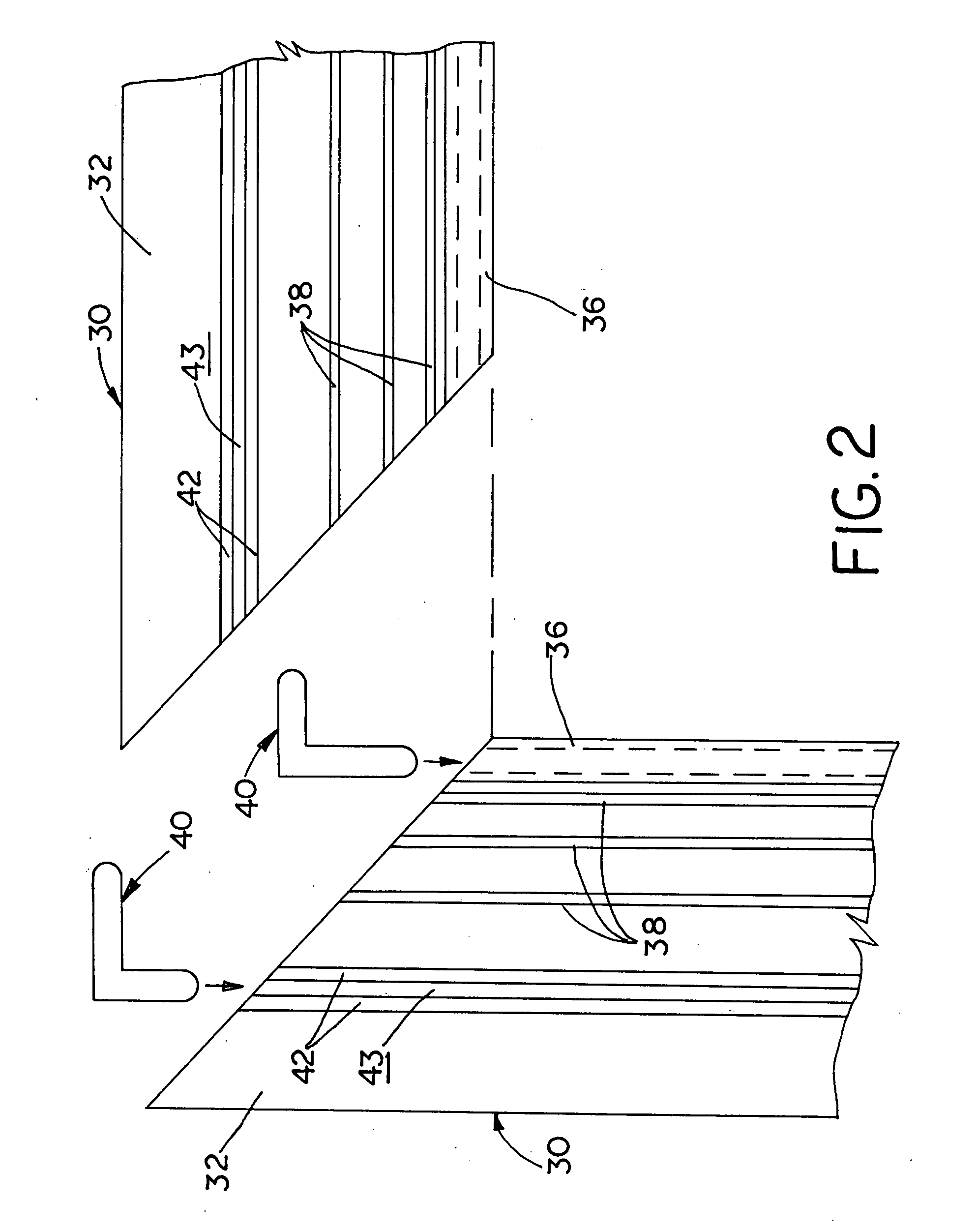
[0021] As shown in FIGS. 2-11, end wall sub-frame 20 is constructed from four main extrusion members 30 interconnected end to end using key-locked miter joints. Each main extrusion me...


PUM


Abstract

The slide-out room is constructed from monocoque laminate wall panels interconnected by an end wall sub-frame. The end wall sub-frame is constructed from unique main extrusion members that are interconnected using key-locked miter joints. Each main extrusion member has a generally Z-shaped cross section, which allows the members to be joined using two joint keys fitted into spaced parallel key channels formed in the main extrusion members. The end wall sub frame also includes secondary extrusion members welded to the main extrusion members and interconnected using a lap joint. The secondary extrusion members have legs that are spaced from the legs of the main extrusion so that the monocoque panels can be fitted and secured between the legs to and from the side walls, ceiling and floor of the slide-out room. A monocoque panel is bonded directly to the outside of the end wall sub-frame to form the slide-out room end wall.

Description

[0001] This invention relates to slide-out rooms of recreational vehicles and an extrusion used in the manufacture of slide-out rooms. BACKGROUND OF THE INVENTION [0002] Slide-out rooms extend and retract from the main body of recreational vehicles (RVs) and other types of manufactured housing to provide additional living space. Typically slide out rooms are mounted on tracks, rails or other supports and are actuated by linkage and screw drives. The design and construction of conventional slide-out rooms present several present practical problems in RV and other manufactured housing applications. [0003] Because slide-out rooms are extended and retracted from the main body of the RV, the slide-out rooms must be constructed to minimize weight, without compromising structural integrity. Reducing the weight of slide out rooms allows manufacturers to build larger slide-out rooms without increasing the power and size of the actuating mechanisms. To reduce weight and simplify construction,...

Claims


Application Information

Patent Timeline
Patent Type & Authority Applications(United States)
IPC IPC(8): B60P3/34
CPCB62D33/08B60P3/34
Inventor GARDNER, STEWART E.
Owner R N R INT
Why Eureka
Try Eureka