
System and method for in-context volume visualization using virtual incision

a virtual incision and volume technology, applied in the field of volume rendering, can solve the problems of inability to apply importance-driven visualization and the loss of the context surrounding an important feature, and achieve the effect of easy evaluation

Inactive Publication Date: 2007-08-23
SIEMENS MEDICAL SOLUTIONS USA INC
View PDF0 Cites 18 Cited by
  • Summary
  • Abstract
  • Description
  • Claims
  • Application Information

AI Technical Summary

Benefits of technology

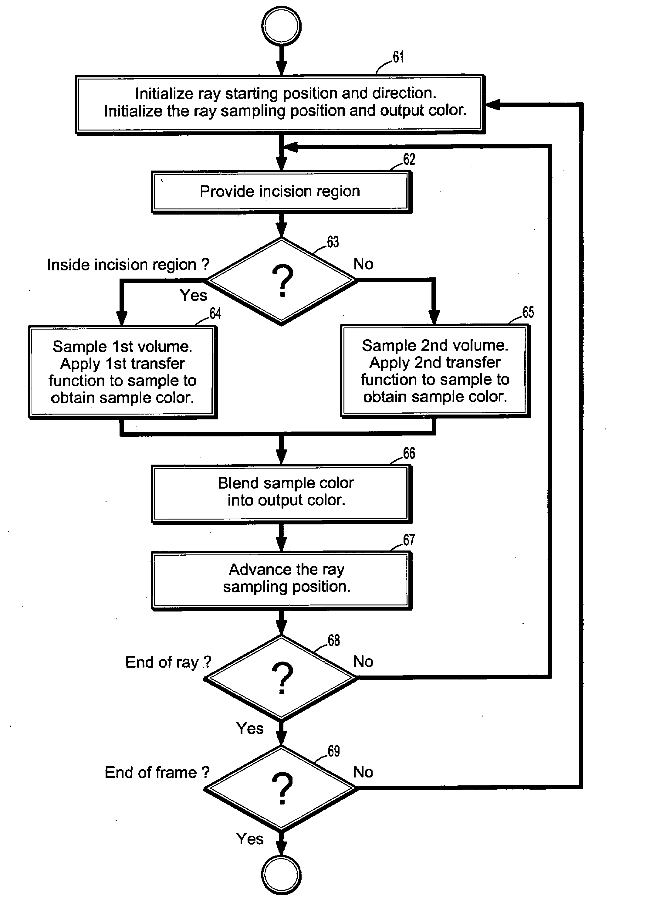
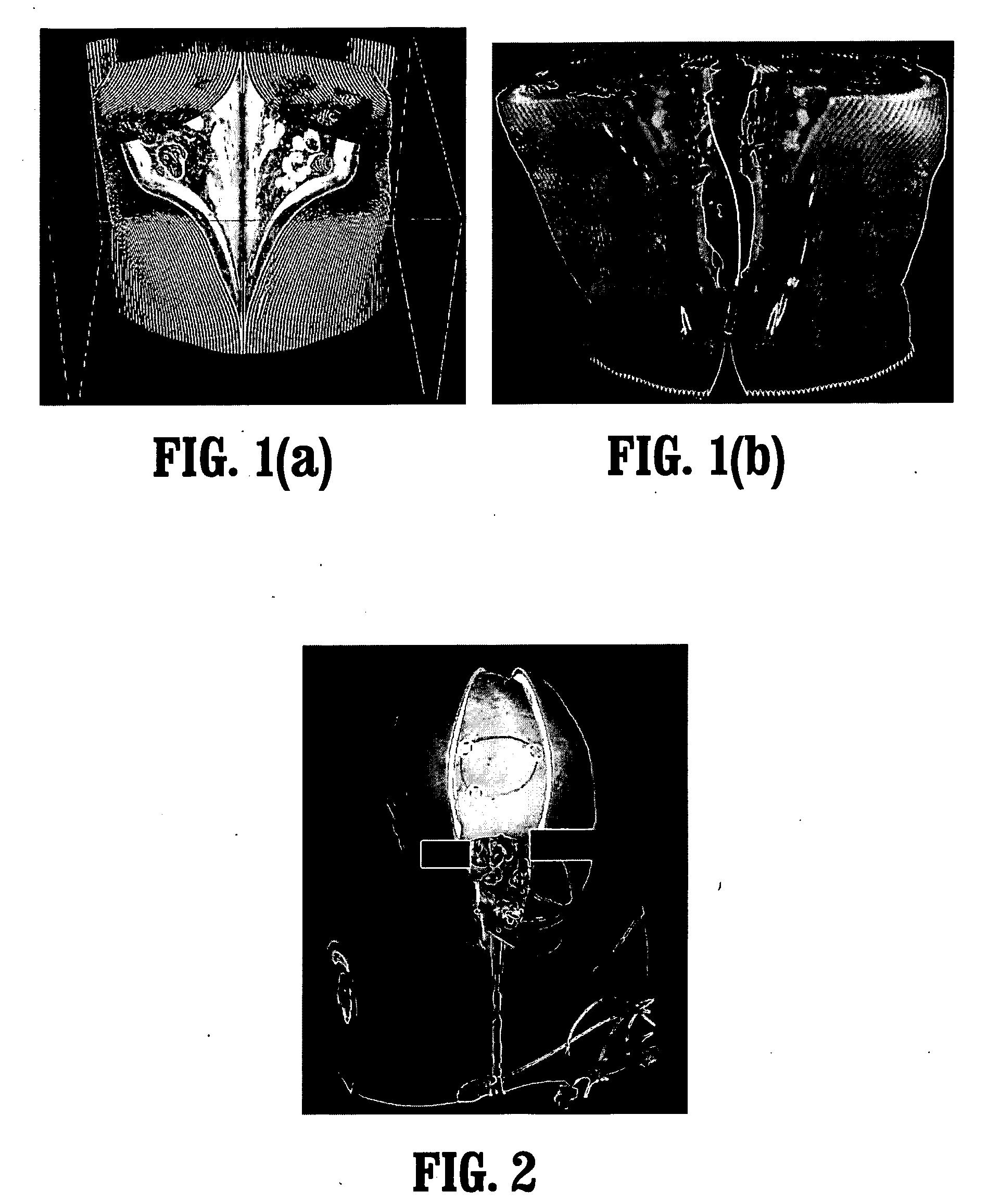
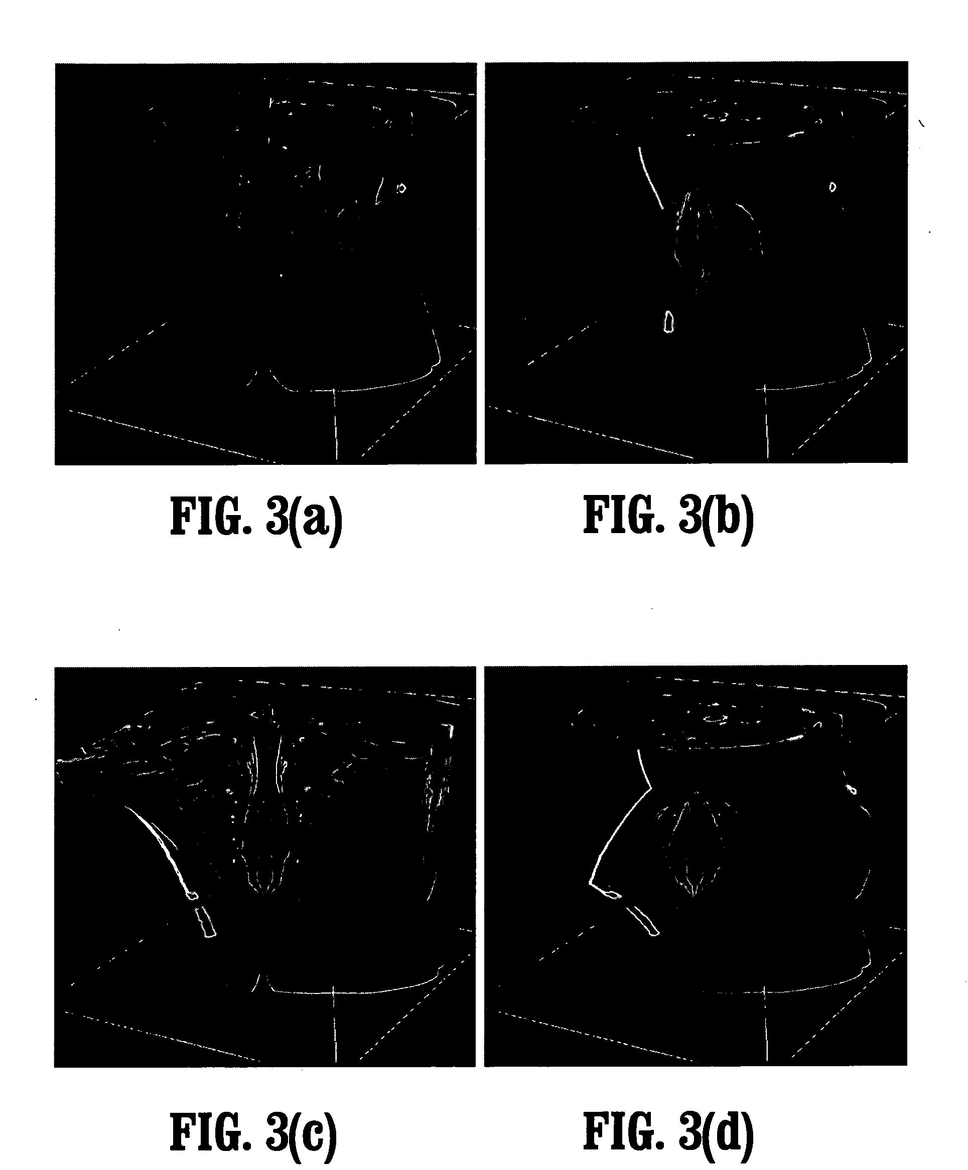
[0007]Exemplary embodiments of the invention as described herein generally include methods and systems for virtual incision rendering that allows visualization of certain anatomical features in the data set in the context of other information. For example, a fractured bone can be shown in the context of bleeding in the surrounding tissue, whereas in traditional volume rendering the surrounding tissue with the bleeding would be lost because a transfer function that shows only bone would be used. According to an embodiment of the invention, the incision area is defined using a virtual incision plane and the distance to viewing point in space. Fragments close to the incision plane and to the viewing point are removed or rendered using a different transfer function. Since it is easy to evaluate the distance of a fragment to the area during rendering, the parameters controlling the area can be changed interactively. Furthermore, the volume surroun

Problems solved by technology

However, by removing occluding features using the transfer function, the context surrounding an important feature is lost.
Consequently, importance-driven visualization cannot be applied in this case.

Method used


Image

  • System and method for in-context volume visualization using virtual incision
  • System and method for in-context volume visualization using virtual incision
  • System and method for in-context volume visualization using virtual incision

Examples


Embodiment Construction

[0031]Exemplary embodiments of the invention as described herein generally include systems and methods for in-context volume visualization. Accordingly, while the invention is susceptible to various modifications and alternative forms, specific embodiments thereof are shown by way of example in the drawings and will herein be described in detail. It should be understood, however, that there is no intent to limit the invention to the particular forms disclosed, but on the contrary, the invention is to cover all modifications, equivalents, and alternatives falling within the spirit and scope of the invention.

[0032]As used herein, the term “image” refers to multi-dimensional data composed of discrete image elements (e.g., pixels for 2-D images and voxels for 3-D images). The image may be, for example, a medical image of a subject collected by computer tomography, magnetic resonance imaging, ultrasound, or any other medical imaging system known to one of skill in the art. The image may ...


PUM


Abstract

A method for volume rendering a digitized medical image includes providing a digitized medical image volume comprising a plurality of intensities on a 3-dimensional grid of points, providing a projection plane comprising a 2-dimensional lattice of points onto which rendering rays are projected from a viewing point through said image volume, advancing a sampling point along a ray through said image volume, generating an incision region within said image volume, determining whether said sampling point is within said incision region, wherein a first transfer function is applied to a sample value interpolated from a first volume if said sampling point is within the incision region, and a second transfer function is applied to a sample value interpolated from a second volume if said sampling point is outside the incision region, and accumulating the output of the transfer function.

Description

CROSS REFERENCE TO RELATED UNITED STATES APPLICATIONS[0001]This application claims priority from: “AN EFFICIENT DISPLAY TECHNIQUE FOR VIRTUAL INCISION USING PROCEDURAL OPENING AND DEFORMATION FOR IN-CONTEXT VOLUME VISUALIZATION”, U.S. Provisional Application No. 60 / 775,193 of Engel, et al., filed Feb. 21, 2006, the contents of which are incorporated herein by reference.TECHNICAL FIELD[0002]This disclosure is directed to volume rendering, in particular to in-context volume visualization of the interior of a volumetric image.DISCUSSION OF THE RELATED ART[0003]The underlying principle of direct volume rendering is to sample a volume dataset along rays in an arbitrary direction and to blend these samples together in a frame buffer. Before being blended, the densities read in the volume are converted to colors (RGBA) with a transfer function that is often encoded as a lookup table. For this reason, the blending is often referred to as alpha-blending. When a sufficient quantity of samples...

Claims


Application Information

Patent Timeline
IPC IPC(8): G06T17/00A61B6/03G06T15/08
CPCG06T15/08
Inventor ENGEL, KLAUSWILLIAMS, JAMES
Owner SIEMENS MEDICAL SOLUTIONS USA INC
Learn More