Ultra wide band wireless optical endoscopic device

Inactive Publication Date: 2007-08-23
KARL STORZ ENDOVISION INC
View PDF23 Cites 23 Cited by
  • Summary
  • Abstract
  • Description
  • Claims
  • Application Information

AI Technical Summary

Benefits of technology

[0014] It is therefore desired to provide an improved video imaging system for us

Problems solved by technology

It is estimated that between one in 6,000 to one in 8,000 general anesthesia procedures result in death.
The foremost obstacles encountered by the anesthesiologist include; the remoteness of the location where the tube is to be positioned, the consequent restriction of view as the tube is inserted, variations and anomalies in the anatomy of the patients, an uncomfortable and unnatural position for the anesthesiologist while holding the instrument, the potential need to change blades during the procedure, and the necessity for rapid intubation.
In addition, the ventilator is not yet in operation.
This delays the operation and extends the patient's time under anesthesia.
This extension of time while under anesthesia may have very serious consequences, especially for elderly patients.
However, such systems typically use an illumination source, which supplies illuminating light to the area ahead of the device via an illumination cable, and transmit images picked up by the CCD back to a video monitor via an image cable.
The cabling and light guides can add complexity and to the system and increase the corresponding size and weight of the device.
This may take an unacceptable amount time for the physician to thread the bundle into the tube if the device

Method used


Image

  • Ultra wide band wireless optical endoscopic device
  • Ultra wide band wireless optical endoscopic device
  • Ultra wide band wireless optical endoscopic device

Examples


Embodiment Construction

[0055] Referring now to the drawings, wherein like reference numerals designate corresponding structure throughout the views.

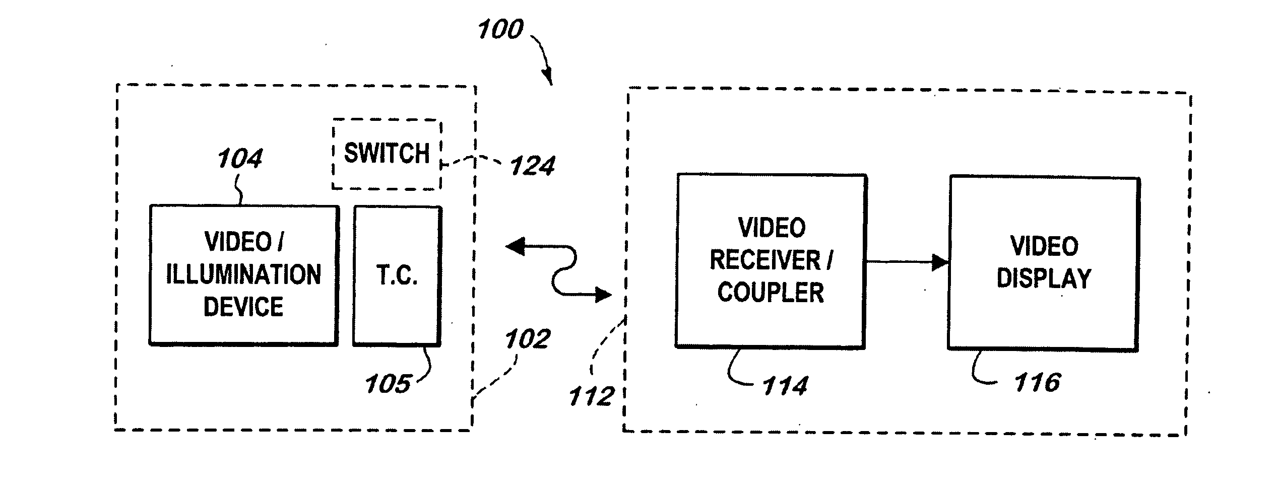
[0056] A video system 100 for use with an endoscopic device 102 is depicted in FIG. 1. It is contemplated that the endoscopic device 102 may comprise, for example, a laryngoscope 130 as depicted in FIGS. 4-6, or an endoscope 170 as depicted in FIGS. 7-8.

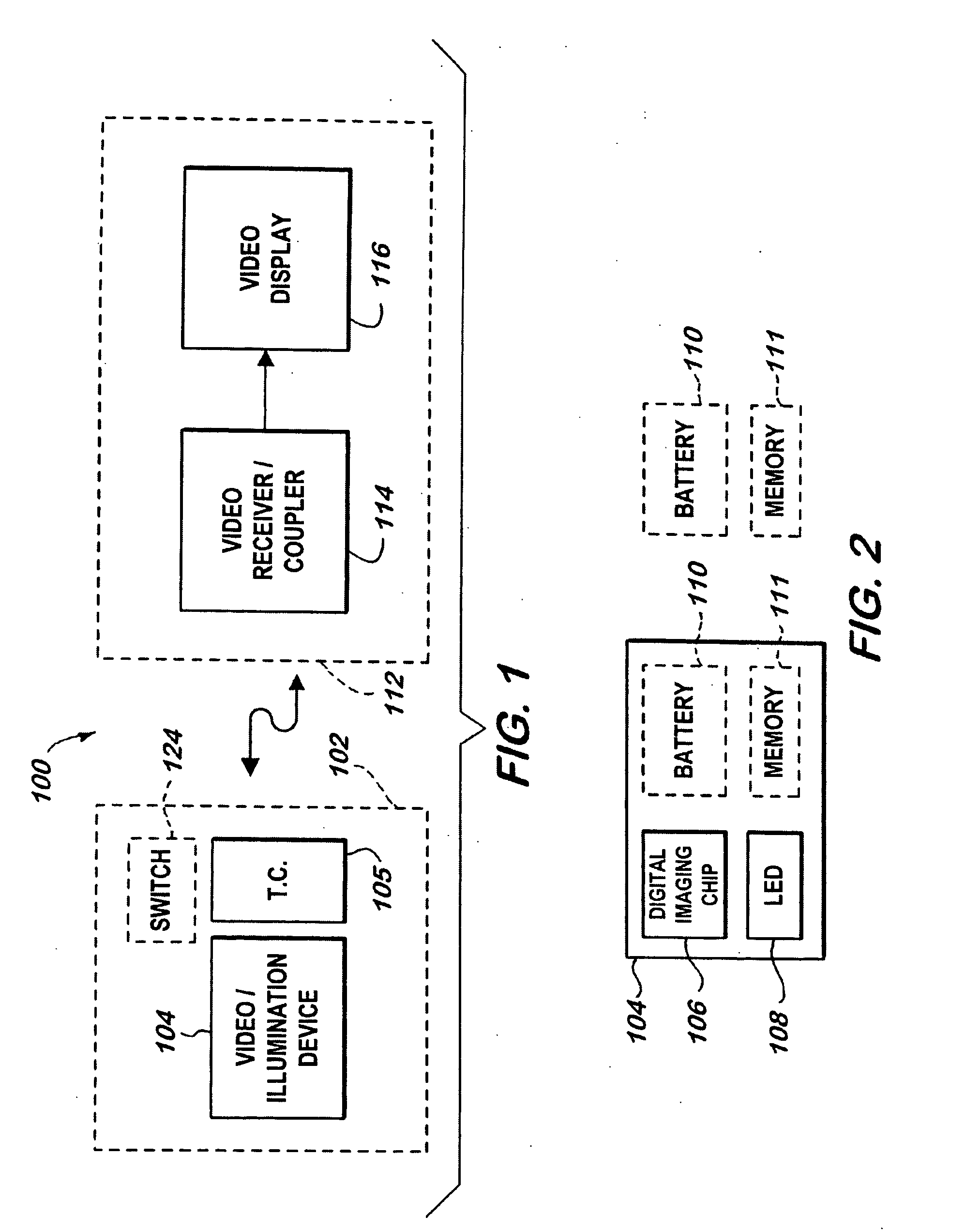
[0057] A video / illumination device 104 is located in endoscopic device 102 and may comprise a digital imaging chip 106, an LED 108, a power source 110 such as a battery, and a memory 111 as illustrated in FIG. 2. Alternatively, it is contemplated that video / illumination device 104 may comprise digital imaging chip 106 and LED 108 only, with the battery 110 and memory 111 positioned in the handle 132, which is represented by the broken line drawings in FIG. 2 of battery 110 and memory 111. In this configuration, electrical power would be transmitted to LED 108 and digital image chip 106 from the handle via a c...


PUM


Abstract

A video endoscopy system for displaying an area to be viewed to a user, the system providing for wireless transmission via UWB signal technology of image data representative of the area to be viewed. The video endoscopy system uses an LED and a battery for providing illuminating light to the area to be viewed. The video endoscopy system also uses a digital imaging chip for picking up reflected light from the area to be viewed and generating image data representative of the reflected light, which in turn is wirelessly transmitted to a video system for display to the user.

Description

CROSS-REFERENCE TO RELATED APPLICATIONS [0001] This application is a continuation-in-part of U.S. patent application Ser. No. 11 / 358,201 filed Feb. 21, 2006.FIELD OF THE INVENTION [0002] The invention relates to a video endoscopic device, and more particularly to a wireless transmitting endoscopic device using an UWB signal format for use in non-invasive surgical and intubation procedures. BACKGROUND OF THE INVENTION [0003] In the United States, approximately 20 million patients are operated on and anesthetized each year. Approximately 50% of surgeries are performed using general anesthesia, which means the patient is put to sleep and the ventilation and other physiological functions are monitored. While anesthetized, the patient's breathing functions are temporarily disabled. Ventilation is therefore supplied to the patient by the anesthesiologist during the procedure. [0004] Ventilation is provided through an endotracheal tube. This tube is inserted into the trachea, and it is clo...

Claims


Application Information

Patent Timeline
IPC IPC(8): B60Q1/124
CPCA61B1/00016A61B1/00105A61B1/042A61B1/00032A61B1/267A61B1/0684A61B1/05
Inventor BIRNKRANT, DASHIELL
Owner KARL STORZ ENDOVISION INC
Why Eureka
Try Eureka