Non-contact support platforms for distance adjustment

a technology of non-contact support and distance adjustment, which is applied in the direction of work benches, work tools storage, bearings, etc., can solve the problems of critical failure of inspection or photolithography process, relative slow time response, and inability of the focusing mechanism to compensate for local wafer distortion, etc., and achieve the effect of combined effective stiffness and effective rigid floating

Active Publication Date: 2007-08-23
COREFLOW SCI SOLUTIONS
View PDF38 Cites 90 Cited by
  • Summary
  • Abstract
  • Description
  • Claims
  • Application Information

AI Technical Summary

Benefits of technology

[0062] Furthermore, in accordance with some preferred embodiments of the present invention, the apparatus is further provided with an effectively rigid floating relatively thin and wide handling element for holding or moving the object, the element is adapted to be supported by an AM-stiff fluid-cushion aimed to create combined effective stiffness.

Problems solved by technology

For example, a relatively heavy chuck, may result in a relatively slow time response.
A different problem of malfunctioning may occur if a sub-micron particle, having for example, a size of 0.5 micrometer or more trapped between a wafer and the chuck, e.g., when the wafer is clamped by the chuck, for example, by vacuum or electrostatic mechanisms.
The particle may cause local distortion of the wafer facing surface, which may result in a critical failure of, for example, inspection or photolithography process.
Such a particle may generate non-parallelism of local nature (small bump) such that the focusing mechanism may not be able to compensate such local wafer distortion.
Furthermore, contact between substrates (such as silicon wafer), and chucks may results with damage, e.g., by causing backside contamination and / or Electro Static Damage (ESD), or mechanical damage to the wafer.

Method used


Image

  • Non-contact support platforms for distance adjustment
  • Non-contact support platforms for distance adjustment
  • Non-contact support platforms for distance adjustment

Examples


Embodiment Construction

[0100] In the following detailed description, numerous specific details are set forth in order to provide a thorough understanding of the present invention. However, it will be understood by those of ordinary skill in the art that the present invention may be practiced without these specific details. In other instances, well-known methods, procedures, components and circuits have not been described in detail so as not to obscure the present invention.

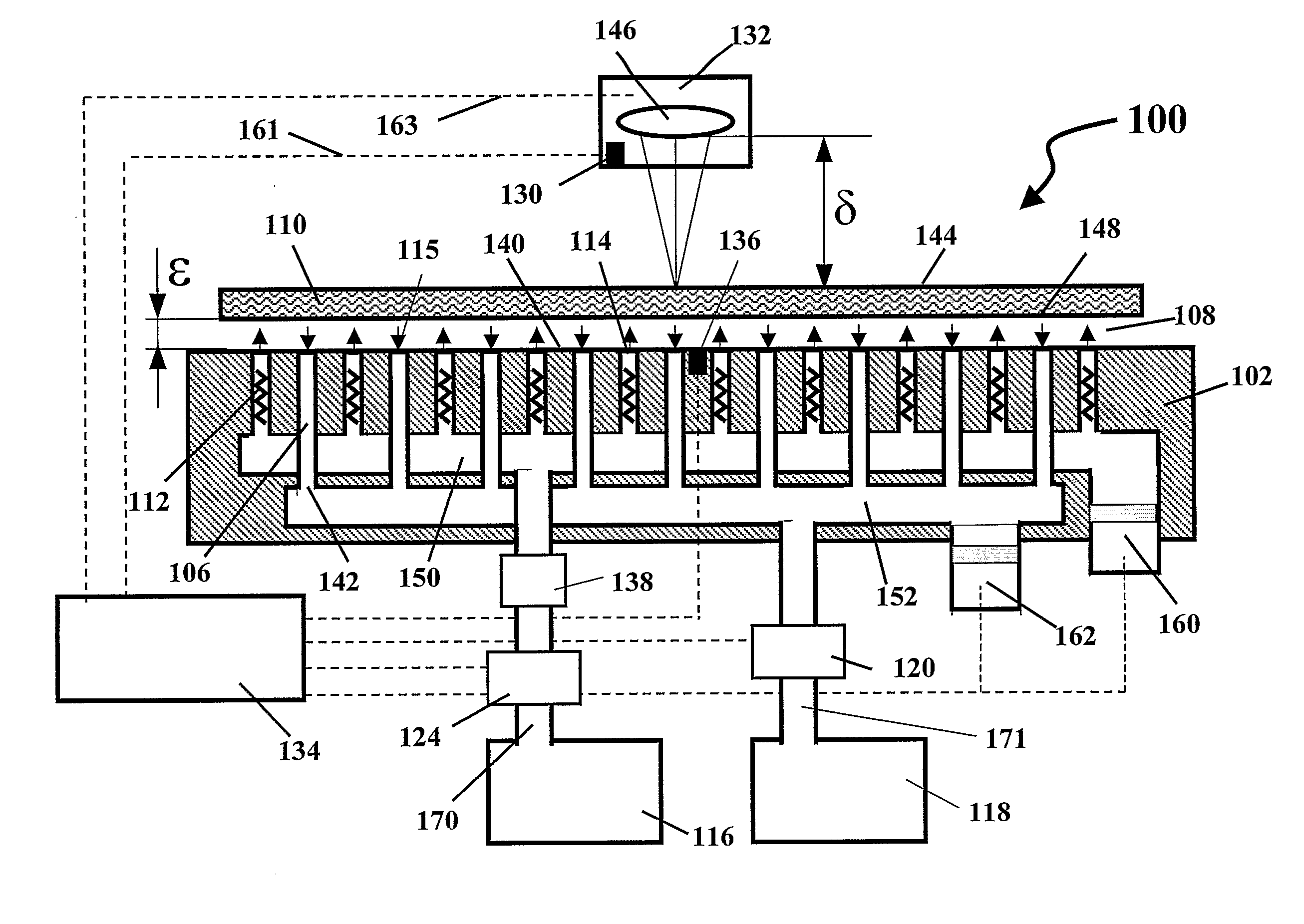
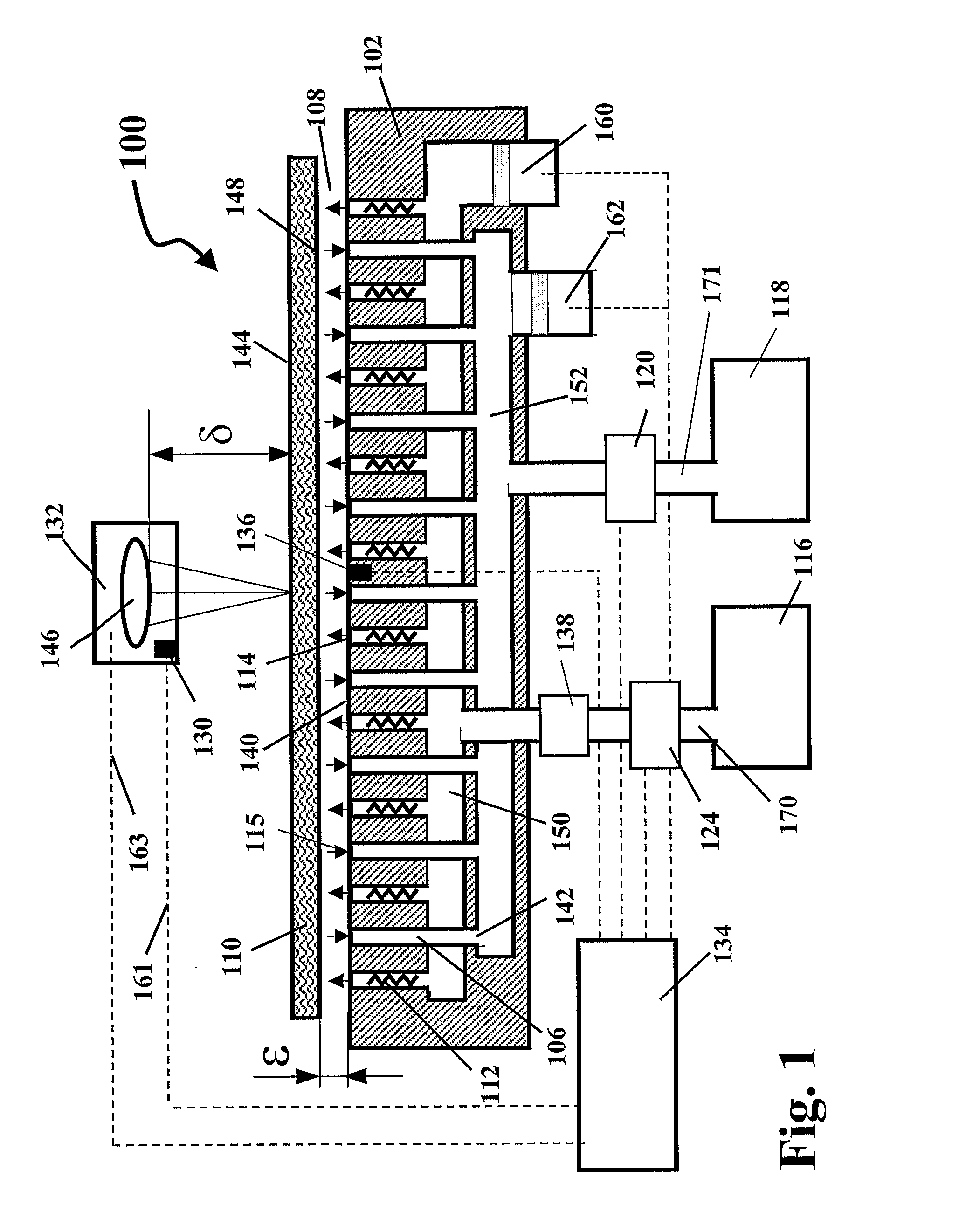
[0101] It will be appreciated that for simplicity and clarity, that the term “adjust” means adjustment of the distance between a facing surface of an object to a reference device or to virtual reference. The terms “focusing” with respect to the present invention is similar to “adjusting” and it frequently used with respect to optical oriented systems. This direction is intuitively regarding to as the vertical direction that is substantially normal to the facing surface of the object. The term “positioning”, with respect to the present ...


PUM

PropertyMeasurementUnit
areaaaaaaaaaaa
sizeaaaaaaaaaa
pressureaaaaaaaaaa

Abstract

An apparatus for supporting a stationary or moving substantially flat object without physical contact on an fluid-cushion. The object floats on a fluid cushion gap, the apparatus aimed for globally or locally adjusting the gap. The apparatus comprising: a first platform for supporting the object without contact, the platform having a substantially flat active surface comprised of one or more sectors, each sector comprising at least one of a plurality of basic cells, each basic cell having at least one of a plurality of pressure outlets fluidically connected through a pressure flow restrictors to a higher-pressure manifold associated with the sector in which the basic cell lies, the higher-pressure manifold is fluidically connected through main supply pipeline to pressurized fluid supply and at least one of a plurality of fluid-evacuation channels fluidically connected to a lower-pressure manifold associated with the sector in which the basic cell lies having main evacuation pipeline; wherein the flow restrictor characteristically exhibiting fluidic return spring behavior; and wherein at least one pressure control valve is interposed with at least one of the two main pipelines of at least one sector for controlling pressure levels of at least one of the two manifolds of that sector.

Description

FIELD OF THE INVENTION [0001] The invention relates to methods and systems of local and global distance adjustment and to non-contact support platforms. BACKGROUND OF THE INVENTION [0002] In existing systems implemented, for example, as part of a process for optical inspection of a surface of a substrate such a semiconductor (SC) thin wafer (700 micrometer and less) of circular shape, or as part of a SC Photolithography process, the wafer is attached to a supporting platform known as a “chuck”, For executing such a process, it is required to vertically move the chuck, for example, relative to an optical device, (or alternatively to move vertically the optical device), in order to adjust in local manner the distance of the wafer facing surface with respect to an optical device. Such systems implement an electro-mechanical and / or a piezoelectric adjusting mechanism in order to provide the focusing in a relatively high degree of accuracy, e.g., in a magnitude of up to very few nanomete...

Claims


Application Information

Patent Timeline
Patent Type & Authority Applications(United States)
IPC IPC(8): G11B11/00B65G49/06H01L21/677H01L21/683
CPCB24B37/30B65G49/065B65G2249/02B65G2249/04H01L21/68714F16C29/025H01L21/67784H01L21/6838B65G2249/045B25H1/02B25H1/00B25H3/00
Inventor YASSOUR, YUVALHARNIK, ARIERICHMAN, HILEL
Owner COREFLOW SCI SOLUTIONS
Why Eureka
Try Eureka