Cardiac harness having diagnostic sensors and method of use

a technology of diagnostic sensors and cardiac harnesses, applied in the field of cardiac harnesses, can solve the problems of affecting the functional performance of the heart, affecting the function of the heart, and often affecting the function of the myocardium,

Inactive Publication Date: 2007-08-23
PARACOR MEDICAL
View PDF12 Cites 43 Cited by
  • Summary
  • Abstract
  • Description
  • Claims
  • Application Information

AI Technical Summary

Benefits of technology

[0010] In accordance with the present invention, a cardiac harness is configured to fit at least a portion of a patient's heart and is associated with one or more electrodes capable of providing defibrillation or pacing functions. In one embodiment, rows or strands of undulations are interconnected and associated with coils or defibrillation and/or pacing/sensing leads. In another embodiment, the cardiac harness includes a number of panels separated by coils or electrodes, wherein the panels have rows or strands of undulations interconnected together so that the panels can flex and can expand and retract circumferentially. The panels of the cardiac harness are coated with a dielectric coating to electrically insulate the panels from an electrical shock delivered through the electrodes. Further, the electrodes are at least partially coated with a dielect

Problems solved by technology

The thinned portion of the myocardium often is functionally impaired, and other portions of the myocardium attempt to compensate.
Cardiac remodeling often subjects the heart wall to increased wall tension or stress, which further impairs the heart's functional performance.
Thus, a cycle can result, in which dilation

Method used


Image

  • Cardiac harness having diagnostic sensors and method of use
  • Cardiac harness having diagnostic sensors and method of use
  • Cardiac harness having diagnostic sensors and method of use

Examples


Embodiment Construction

[0086] This invention relates to a method and apparatus for treating heart failure. It is anticipated that remodeling of a diseased heart can be resisted or even reversed by alleviating the wall stresses in such a heart. The present invention discloses embodiments and methods for supporting the cardiac wall and for providing defibrillation and / or pacing functions using the same system. Additional embodiments and aspects are also discussed in Applicants' co-pending application entitled “Multi-Panel Cardiac Harness” U.S. Ser. No. 60 / 458,991 filed Mar. 28, 2003, the entirety of which is hereby expressly incorporated by reference.

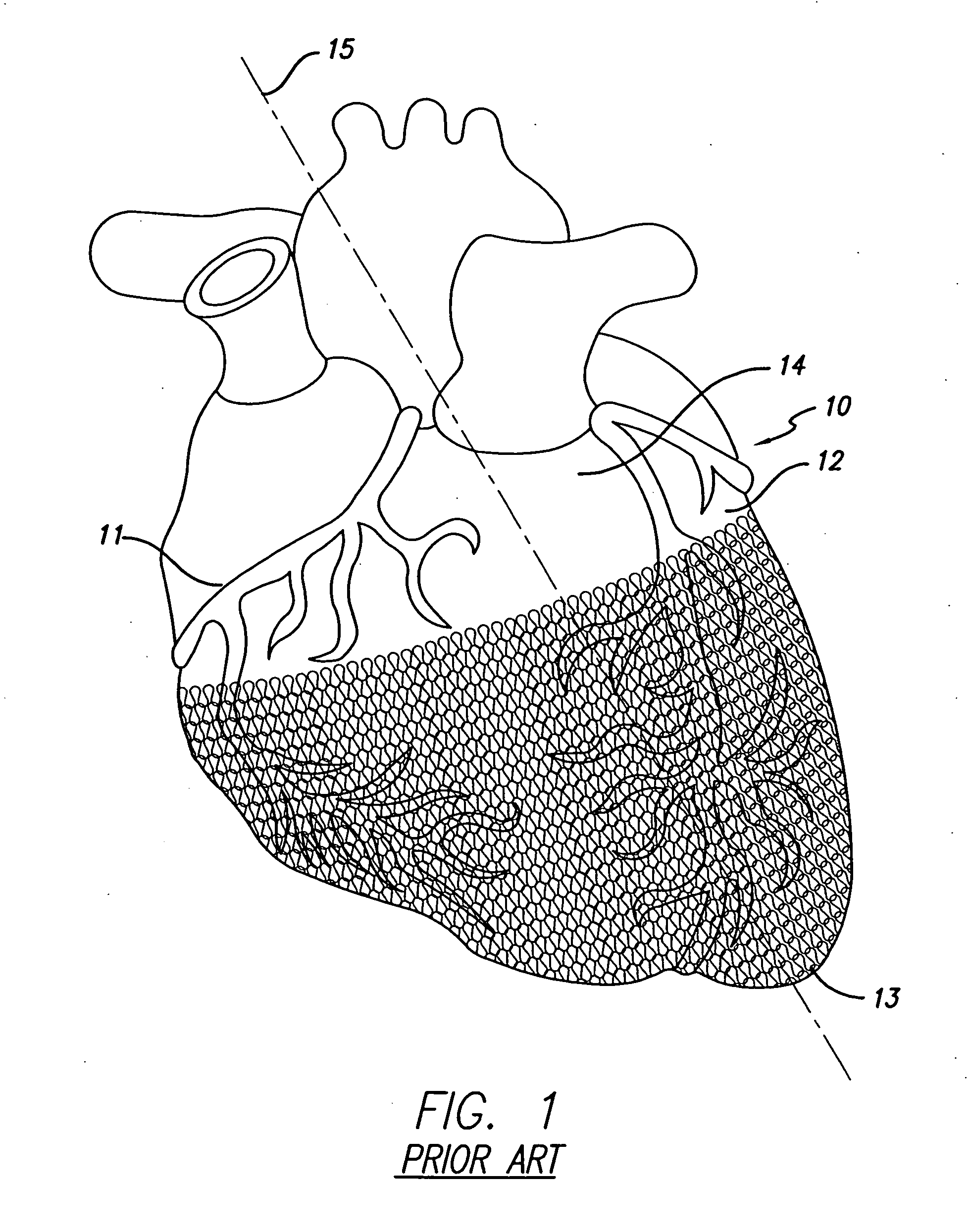
[0087]FIG. 1 illustrates a mammalian heart 10 having a prior art cardiac wall stress reduction device in the form of a harness applied to it. The harness surrounds a portion of the heart and covers the right ventricle 11, the left ventricle 12, and the apex 13. For convenience of reference, longitudinal axis 15 goes through the apex and the AV groove 14. The c...


PUM


Abstract

A cardiac harness adapted to fit generally around a least a portion of a heart includes at least one elastic spring member forming an annular portion that is elastically deformable and at least one sensor disposed on the annular portion for providing a sensor signal representative of cardiac function. The cardiac harness applies a compressive force on the heart during diastole and systole. The sensor is configured to take a measurement of impedance across the heart, impedance across a lung, evoked response of the heart, activation patterns of the heart, acceleration of a portion of the heart, position of a portion of the heart relative to an ultrasonic transmitter, pH on the heart's epicardial surface, blood oxygen saturation of a portion of the heart, or position of a portion of the heart relative to a magnetic field generating device. The cardiac harness and sensor are delivered and implanted on the heart by minimally invasive access.

Description

CROSS-REFERENCES TO RELATED APPLICATIONS [0001] This application is a continuation-in-part of U.S. Ser. No. 10 / 704,376, filed Nov. 7, 2003, which is herein incorporated by reference in its entirety.BACKGROUND OF THE INVENTION [0002] The present invention relates to a device for treating heart failure. More specifically, the invention relates to a cardiac harness configured to be fit around at least a portion of a patient's heart. The cardiac harness includes electrodes attached to a power source for use in defibrillation or pacing. [0003] Congestive heart failure (“CHF”) is characterized by the failure of the heart to pump blood at sufficient flow rates to meet the metabolic demand of tissues, especially the demand for oxygen. One characteristic of CHF is remodeling of at least portions of a patient's heart. Remodeling involves physical change to the size, shape and thickness of the heart wall. For example, a damaged left ventricle may have some localized thinning and stretching of ...

Claims


Application Information

Patent Timeline
IPC IPC(8): A61F2/00A61N1/05A61N1/375
CPCA61F2/2481A61N1/0597A61N1/0587A61F2002/2484
Inventor SCHAER, ALANFISHLER, MATTHEW G.
Owner PARACOR MEDICAL
Why Eureka
Try Eureka