
Sectional crimped graft

a vascular graft and sectional crimping technology, applied in the field of vascular prosthesis, can solve the problems of insignificant longitudinal extension, disadvantageous to have excessive extension subsequent, and the graft not fully recovering to its original unloaded length, so as to limit the overall longitudinal extension, enhance the deployment of the stent-graft, and controllable flexibility and elongation. the effect of length

Inactive Publication Date: 2007-08-23
LIFESHIELD SCI
View PDF15 Cites 35 Cited by
  • Summary
  • Abstract
  • Description
  • Claims
  • Application Information

AI Technical Summary

Benefits of technology

[0006] The present invention provides a sectional crimped graft that allows graft flexibility only where required and thus limits the overall longitudinal extension. The present invention overcomes the disadvantage of fully crimped grafts by controlling the number of crimps per unit length, crimp height, crimp geometry and their location along the graft wall. In so doing, flexibility and elongation can be controllably tailored only in areas where significant anatomical angulation is present. It may also be useful in applications other than stent grafts such as surgical grafts for abdominal and peripheral areas. Limiting the overall graft longitudinal extension also enhances the deployment of the stent-graft into the blood vessel.
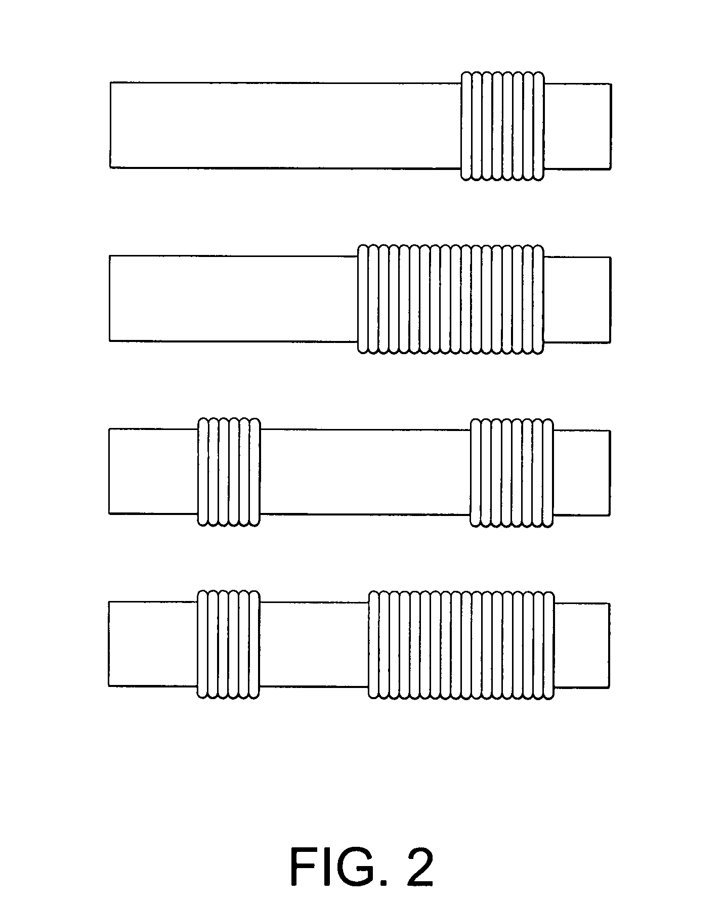
[0007] In accordance with one embodiment of the present invention, crimps are installed only in pre-determined, intermittent locations along the length on the graft. One advantage obtained thereby is to provide needed flexibility to a specific location. Such a graft structure is particularly useful in thoracic stent-graft devices, where a ≧90 degree bend may be present in the treated thoracic aorta. In addition, by minimizing the number of crimps on the graft, the excessive longitudinal extension of the graft is also greatly reduced.
[0008] In accordance with another embodiment of the present invention, various factors of crimps on the graft can be varied depending on the desired characteristics for a specific graft application. Such factors are the height of the crimps, the length of the crimped section, i.e., the number of crimps, and the profile, i.e. the cross-sectional geometry of the crimps. The greater the crimp height and the more crimps, the more the elongation of the graft. The elongation can be reduced by reducing the number of crimps per unit length, reducing the height of the crimps and changing their profile. So, depending on the characteristics or diameter of the body or blood vessel, the degree of the crimping can be varied to provide a better fit to the contour of the vessel wall, provide variable flexibility to better accommodate tortuous anatomy, and reduce graft extensioning.

Problems solved by technology

In certain applications, however, flexibility is desired but significant longitudinal extension is not.
In certain applications, such as endoluminal stent-graft devices used in thoracic, abdominal or peripheral applications, it is disadvantageous to have excessive extension subsequent to implantation.
Additionally, use of a “fully crimped” graft on a thoracic stent-graft has identified issues with graft elongation within the deployment sheath causing the graft to not fully recover to its original unloaded length.
Fully crimped grafts have a significant degree of unwanted elongation extension therefore creating difficulty during deployment.
The stent can easily return to its original length due to shape memory properties, but the graft cannot.
When full graft length recovery is required, herein lies the problem.
The graft expands with the stent at each end of the graft, but due to crimping along its entire length, the graft does not recover to its original length during deployment.
Thus, prior devices have not provided a solution which balances the need to accommodate vessel angulation flexibility and to facilitate deployment with the need to minimize longitudinal extension.

Method used


Image

  • Sectional crimped graft
  • Sectional crimped graft
  • Sectional crimped graft

Examples


Embodiment Construction

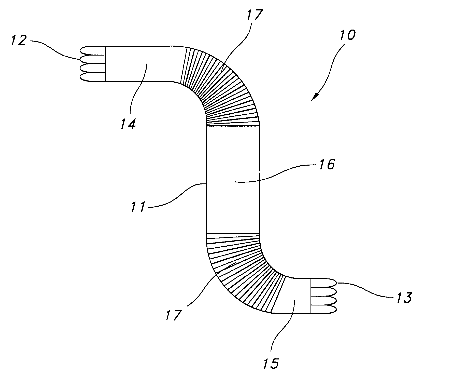
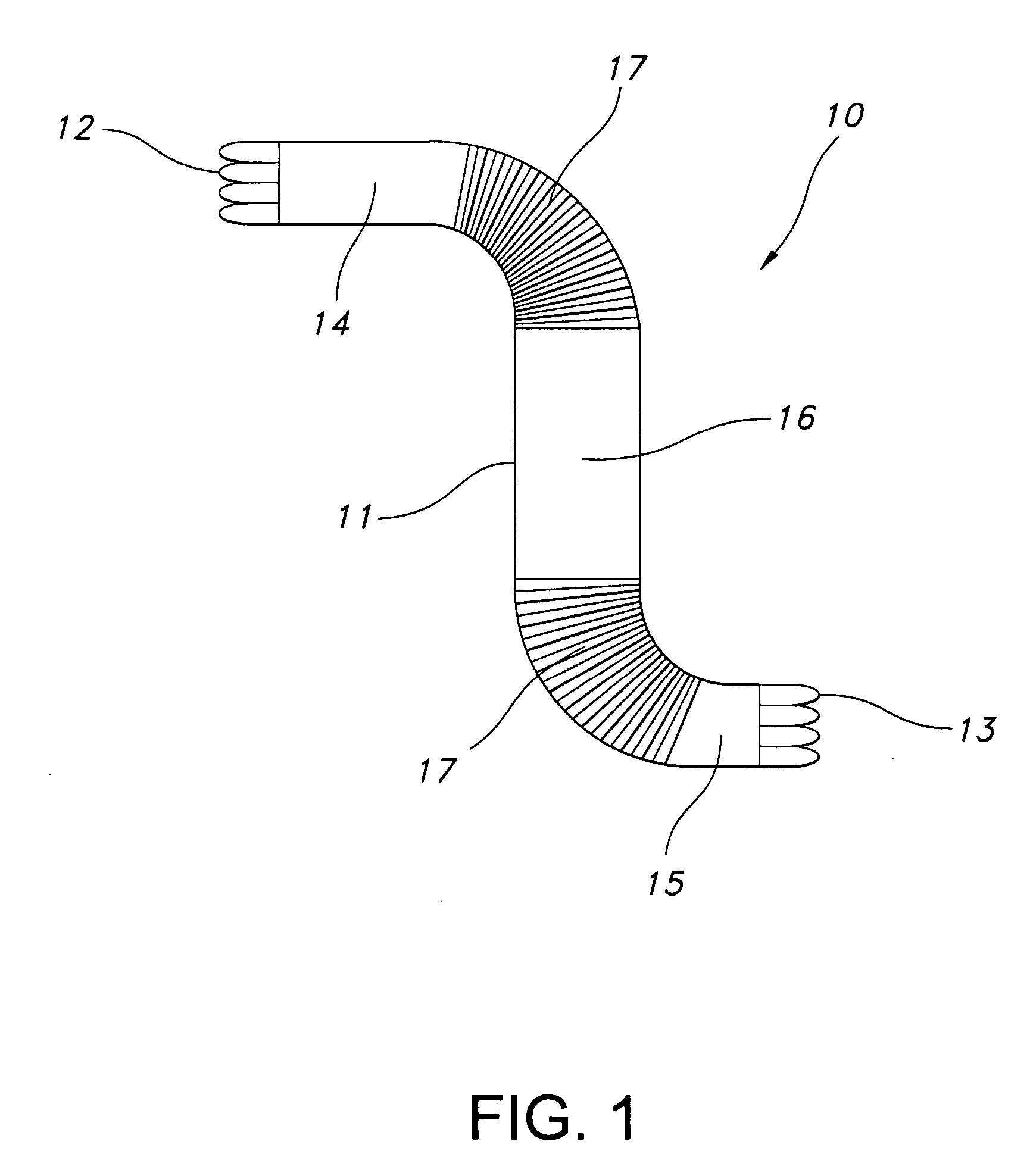
[0018] Referring now to FIG. 1, one aspect of the present invention is provided. Stent-graft 10 is an elongate generally tubular body, desirably a thin walled hollow cylinder 11 having opposed-stent ends, a first open-stent end 12 and a second open end 13. The graft is divided into end portions 14 and 15 adjacent open-stent ends 12 and 13, respectively. The graft 10 has central portion 16 extending longitudinally between the end portions 14 and 15.

[0019] Crimps 17 are incorporated in graft 10, extending from the first end portion 14 towards the central portion 16. Crimps 18 are incorporated on the other side of the graft extending from the second end portion 15 towards the central portion 16. Crimping in the manner shown in FIG. 1 is one example of crimping only on those areas of the graft where flexibility is required. In FIG. 1, the flexibility is needed on the portion that is to be bent or used at a particular angle or curvature. Since this type of flexibility is not required on...


PUM


Abstract

The present invention provides a sectional crimped graft that allows graft flexibility where required and limits the overall longitudinal extension. The present invention overcomes the disadvantage of fully crimped grafts by controlling the number of crimps per unit length, crimp height, crimp geometry and their location along the graft wall, dependent on the particular end-use application. In so doing, flexibility and elongation can be controllably tailored only in areas where significant anatomical angulation is present. It may also be useful in applications other than stent grafts such as surgical grafts for aortic and peripheral areas. Limiting the overall graft longitudinal extension also facilitates the deployment of the stent-graft into the blood vessel.

Description

CROSS-REFERENCE TO RELATED APPLICATION [0001] This application is a continuation of U.S. application Ser. No. 10 / 206,620, filed on Jul. 26, 2002, the contents of which are incorporated herein by reference.FIELD OF THE INVENTION [0002] The present invention relates generally to a vascular prosthesis for repair or replacement of a blood vessel. More particularly, the present invention provides a sectionally crimped vascular graft for repair of damaged or diseased sections of blood vessels, which can be used alone or in combination with a stent to form a stent-graft device. BACKGROUND OF THE INVENTION [0003] Vascular grafts are well known to repair or replace the damaged or diseased portions of body vessels such as blood vessels. It has been a common practice to install crimps in a graft by fully crimping the graft. Crimping provides several advantages. For example, textile grafts are much easier for the surgeon to handle once crimped, because crimping provides a self-supporting featur...

Claims


Application Information

Patent Timeline
Patent Type & Authority Applications(United States)
IPC IPC(8): A61F2/06A61F2/82
CPCA61F2/06A61F2/89A61F2/07
Inventor CASEY, THOMASNELSON, KRISTOFFQUIGLEY, FERGUS
Owner LIFESHIELD SCI
Learn More