Control apparatus capable of economically and reliably controlling electric generator

a control apparatus and electric generator technology, applied in the direction of electric generator control, instruments, roads, etc., can solve the problems of difficult to achieve a high control response, the power generation cost of the alternator is determined as an increase in fuel consumption, etc., to achieve reliably control the power generation operation of the electric generator, prevent over-charge and over-discharge, and reduce the amount of electric power

Active Publication Date: 2007-08-23
DENSO CORP
View PDF7 Cites 28 Cited by
  • Summary
  • Abstract
  • Description
  • Claims
  • Application Information

AI Technical Summary

Benefits of technology

[0023]a decreased amount of electric power, if the power generation cost of the electric generator is determined by the comparator as being higher than the threshold, so as to allow the electric energy storage device to discharge to feed the electrical load.
[0024]With the above configuration, the control apparatus can economically control the power generating operation of the electric generator based on the comparison between the power generation cost of the electric generator and the threshold of power generation cost.
[0025]Further, since the threshold of power generation cost is determined as the function of the SOC of the electric energy storage device, the control apparatus can reliably prevent over-charge and over-disch

Problems solved by technology

Consequently, it is difficult to achieve a high control response and to secure high stability of the power supply bus.
More specifically, the power gene

Method used


Image

  • Control apparatus capable of economically and reliably controlling electric generator
  • Control apparatus capable of economically and reliably controlling electric generator
  • Control apparatus capable of economically and reliably controlling electric generator

Examples


first embodiment

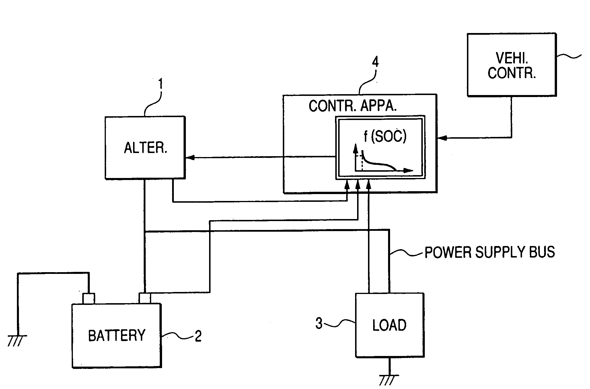
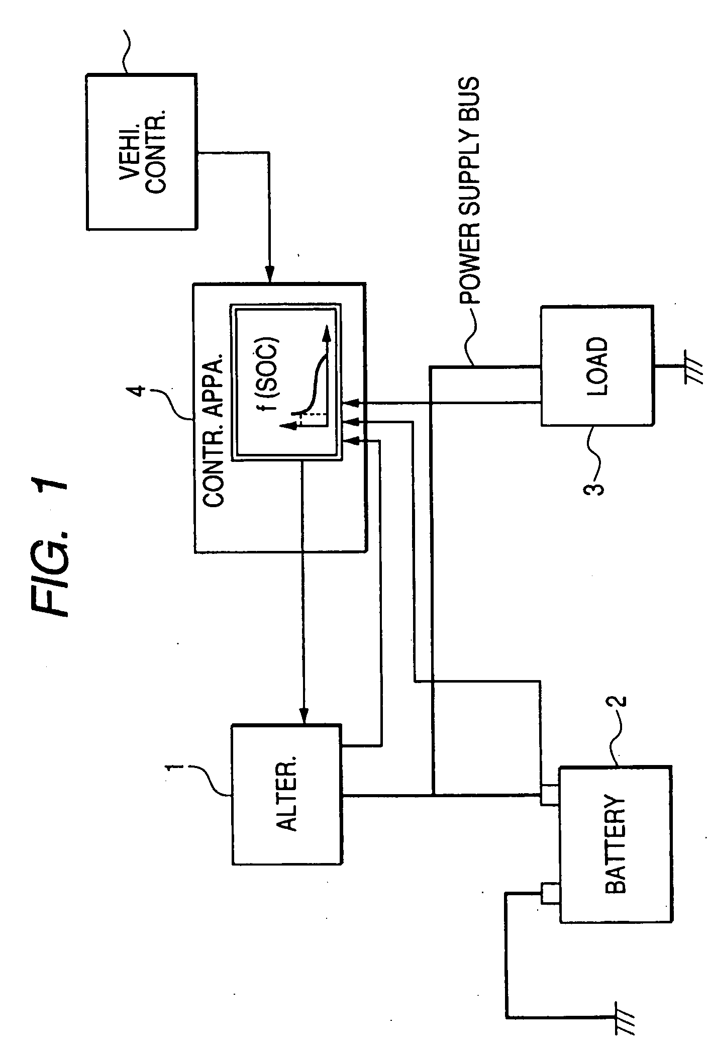
[0070]FIG. 1 shows the overall configuration of an electrical system according to the first embodiment of the invention. The electrical system is designed for use in an automobile.

[0071]As shown in FIG. 1, the electrical system includes an automotive alternator 1, an automotive battery 2, an electrical load 3, and a control apparatus 4.

[0072]The alternator 1 is configured to be driven by an internal combustion engine (not shown) of the automobile to generate electric power. The alternator 1 is electrically connected, via a power supply bus, to both the battery 2 and the electrical load 3, so that it can charge the battery 2 and can feed the electrical load 3. The battery 2 can also feed the electrical load 3 by discharging. The control apparatus 4 works to control the power generating operation of the alternator 1 based on information from the battery 2, the electrical load 3, and a vehicle controller 5.

[0073]The information from the battery 2 includes, for example, the State of Cha...

example 1

[0093]In this example, a power transistor (not shown), which is used to control the field current supply to a field winding of the alternator 1, is turned on when the power generation mode of the alternator 1 is selected, is turned off when the power generation stop mode is selected, and kept in the previous state of on / off operation thereof when the keeping mode is selected.

[0094]More specifically, referring to FIG. 6, when the power generation cost Cg of the alternator 1 is lower than the threshold Cp, as indicted at the point X1 in the figure, the power generation mode is selected. Thus, the alternator 1 enters the power generation mode to generate electric power, thereby both feeding the electrical load 3 and charging the battery 2. As a result, the SOC of the battery 2 is increased. On the contrary, when the power generation cost Cg of the alternator 1 is higher than the threshold Cp, as indicated at the point X2 in FIG. 6, the power generation stop mode is selected. Thus, the ...

example 2

[0096]In this example, the control apparatus 4 controls the power generating operation of the alternator 1 using a hybrid of the power generation cost control and the power balance control.

[0097]More specifically, the control apparatus 4 first determines the amount of electric power to be discharged from (i.e., +) or charged into (i.e., −) the battery 2 (to be simply referred to as charge / discharge power of the battery 2 hereinafter).

[0098]It should be noted that the power generation cost Cg of the alternator 1 is taken into consideration in the determination of the charge / discharge power of the battery 2.

[0099]Then, the control apparatus 4 determines the amount of electric power required to be generated by the alternator 1 by subtracting the charge / discharge power of the battery 2 from the amount of electric power required by the electrical load 3.

[0100]After that, the control apparatus 4 controls the alternator 1 to generate the determined amount of electric power.

[0101]Consequent...


PUM


Abstract

According to the present invention, a control apparatus for an electric generator includes a power generation cost determiner determining a power generation cost of the generator, a threshold determiner determining a threshold of power generation cost as a function of a state of charge of an electric energy storage device, a comparator comparing the power generation cost of the generator with the threshold, and a controller. When the power generation cost of the generator is lower than the threshold, the controller controls the generator to generate an increased amount of electric power, so as to both charge the electric energy storage device and feed an electrical load. Otherwise, when the power generation cost of the generator is higher than the threshold, the controller controls the generator to generate a decreased amount of electric power, so as to allow the electric energy storage device to discharge to feed the electrical load.

Description

CROSS-REFERENCE TO RELATED APPLICATION[0001]This application is based on and claims priority from Japanese Patent Application No. 2006-44301, filed on Feb. 21, 2006, the content of which is hereby incorporated by reference into this application.BACKGROUND OF THE INVENTION[0002]1. Technical Field of the Invention[0003]The present invention relates generally to power generation controls for electric generators. More particularly, the invention relates to a control apparatus for an electric generator, which can economically and reliably control the power generating operation of the electric generator.[0004]2. Description of the Related Art[0005]In conventional electrical systems for automobiles, a control apparatus (or a voltage regulator) generally controls the power generating operation of an automotive alternator so as to keep the voltage of a power supply bus within a predetermined range.[0006]More specifically, the control apparatus determines a change in the voltage of the power ...

Claims


Application Information

Patent Timeline
IPC IPC(8): G05D11/00G06F15/02H02P9/04B60R16/03B60R16/04H01M10/44
CPCY02T10/92H02J7/1446E01C11/227E01C19/506E02B13/00
Inventor YAMAMOTO, HIROYOSHISHIMOYAMA, TAKESHITANAKA, KATSUNORIKATO, AKIRA
Owner DENSO CORP
Why Eureka
Try Eureka