Insulated concrete form system

Inactive Publication Date: 2007-08-30
GEILEN ROY J
View PDF18 Cites 17 Cited by
  • Summary
  • Abstract
  • Description
  • Claims
  • Application Information

AI Technical Summary

Benefits of technology

[0010] In a preferred embodiment for the insulated concrete form system of this invention, the EPS panels each have a thickness of about 10 inches, are about 48 inches wide, and have a height of 96 inches or 108 inches depending upon building specifications. Tongue and groove configurations are cut into opposed side edges of each panel to assist in erecting the walls of the structure by interlocking adjacent panels with opposed tongues and grooves. An expanding foam adhesive may be applied to the interlocking joints, and rebar is disposed within the columnar voids of the panels and the beam voids of the panels to ensure structural integrity in accord with design specifications. Of course, the rebar is placed in those voids prior to the concrete pour, and the rebar within the columnar voids is mechanically fixed to the rebar segments extending from the slab or foundation, all according to standard construction techniques.
[0011] Windows and doors may be pre-cut in the wall panels before delivery to the site, and electrical and plumbing chases may also be pre-formed according to the building specifications.

Problems solved by technology

However, the presence of the EPS panels significantly enhances the insulating properties of the resulting structure as a result of the low thermal conductivity of EPS.
Perhaps due to the complexity of existing systems, most of the construction industry has been reluctant to adopt and utilize these methods and techniques.

Method used


Image

  • Insulated concrete form system
  • Insulated concrete form system
  • Insulated concrete form system

Examples


Embodiment Construction

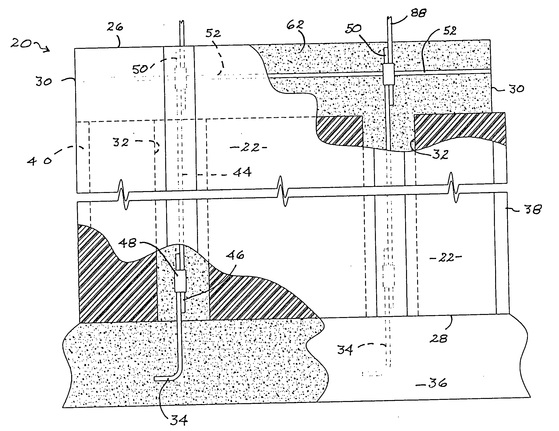
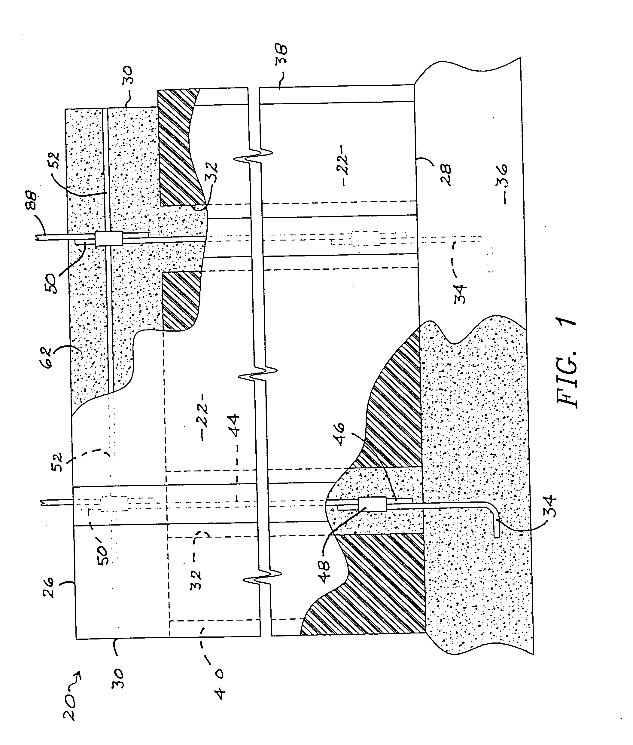
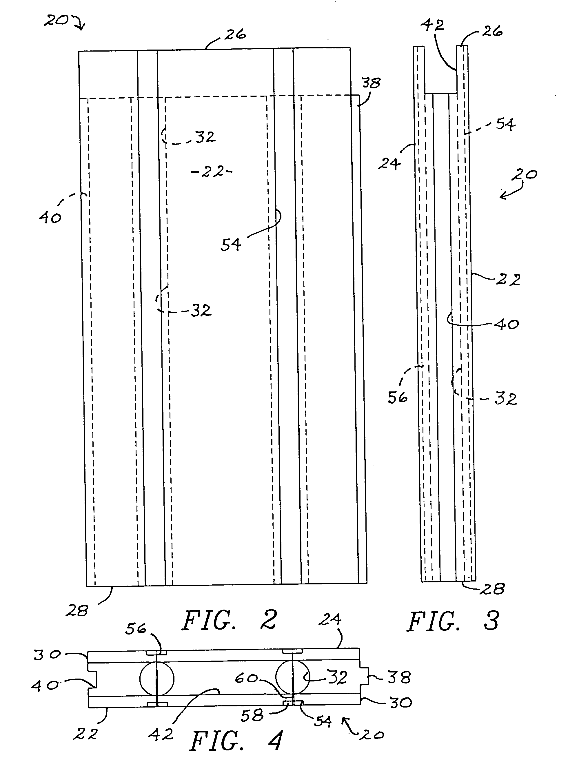
[0027] Referring first to the views of FIGS. 1-4, a wall panel of the present invention is generally indicated as 20. Each of the wall panels 20 have an exterior wall surface 22 and an interior wall surface 24. Wall panels 20 are preferably formed from EPS, and are defined by a top edge 26, a bottom edge 28, and opposed side edges 30. As best seen in the views of FIGS. 1 & 4, columnar wall voids 32 are formed within the wall panels 20 and extend from bottom edge 28 upwardly through top edge 26. As clearly shown in the view of FIG. 1, the columnar wall voids 32 are disposed so as to be in registry with slab rebar segments 34 that are disposed within slab or foundation 36 and extend upwardly therefrom. Slab rebar segments 34 are typically J-bar segments as shown in the view of FIG. 1.

[0028] As perhaps best seen in the plan view of FIG. 4, side edges 30 further comprise a tongue 38 on one of the side edges 30 and a corresponding groove 40 formed in the other of the side edges 30. Thus...


PUM

PropertyMeasurementUnit
heightaaaaaaaaaa
heightaaaaaaaaaa
heightaaaaaaaaaa

Abstract

An insulated concrete form system for constructing the exterior walls and gable ends of a structure is disclosed using expanded polystyrene forms that interconnect and are bonded to each other and to the structure's slab or foundation with concrete. Internal, substantially columnar voids are provided in each of the panel forms and both the interior and the exterior surfaces of the walls and gable ends may be finished with a variety of finish materials using furring strips that are incorporated into the interior and exterior surfaces of the forms.

Description

BACKGROUND OF THE INVENTION [0001] 1. Field of the Invention [0002] The present invention relates to an insulated concrete form system for constructing the exterior walls and gable ends of a structure on an existing slab or foundation. The concrete form system includes wall panels, corner panels, and gable panels, all preferably formed from expanded polystyrene (EPS). Voids are provided in the panels for the introduction of concrete, thereby providing structural integrity for the resulting structure. [0003] 2. Description of the Prior Art [0004] Since at least as early as the 1950's, it has been known to use foamed plastic blocks for the construction ofvarious structures. Such blocks typically interlock one with another and include various forms of voids formed therein to receive a concrete slurry, providing structural integrity. Most such blocks are formed from EPS, and the prior art also teaches covering the outer skins of the blocks with oriented strand board to provide what is k...

Claims


Application Information

Patent Timeline
Patent Type & Authority Applications(United States)
IPC IPC(8): E04B2/00E02D27/32E04C1/00
CPCE04B2/8629E04C2/205E04B2002/867
Inventor GEILEN, ROY J.
Owner GEILEN ROY J
Why Eureka
Try Eureka