Shape Of Combustion Chamber For Direct-Injection Diesel Engine

a technology of direct injection and combustion chamber, which is applied in the direction of combustion engines, machines/engines, pistons, etc., can solve the problems of pm generation, nox is liable to be generated in a complete combustion state, and induces pm, so as to reduce nox and reduce nox. , the effect of increasing the air utilization ra

Active Publication Date: 2007-08-30
YANMAR POWER TECHNOLOGY CO LTD
View PDF4 Cites 14 Cited by
  • Summary
  • Abstract
  • Description
  • Claims
  • Application Information

AI Technical Summary

Benefits of technology

[0019] According to the first aspect of the present invention, a flame or a mixture air staying inside of the combustion chamber can be allowed to strongly flow into a main chamber from mainly each of the round portions at the polygonal opening in an expansion stroke, thereby promoting the mixture of the air and the fuel in the main chamber. As a consequence, an air utilization rate can be increased in the expansion stroke, and further, a combustion speed can be increased. Thus, even if measures for reducing NOx are taken, for example, an injection timing is retarded or an EGR rate is increased, a PM can be reduced. In other words, it is possible to reduce NOx and the PM at the same time. In addition, even if an injector of a relatively low injection pressure is used, the PM can be reduced.
[0020] According to the second aspect of the present invention, the angle of the round portion at the opening of the combustion chamber, that is, an angle relative to an adjacent straight portion becomes optimum, thereby favorably forming a strong flow from mainly the round portion in the expansion stroke.
[0021] According to the third aspect of the present invention, the flame or the mixture air flowing from the combustion chamber into the main chamber uniformly flows from each of the round portions at the opening. As a consequence, the air utilization rate in the main chamber can be increased, and further, the mixture can be promoted.
[0022] According to the fourth aspect of the present invention, the angle of the round portion at the opening of the combustion chamber becomes optimum, thereby favorably forming a strong flow from mainly the round portion in the expansion stroke.
[0023] According to the fifth aspect of the present invention, the shape of the circumferential wall of the combustion chamber can allow a swirl flow to be held inside of the combustion chamber, and further, the strong flow to be injected from mainly the round portion in the expansion stroke. In particular, a strong flow disturbance is generated in the vicinity of the boundary between the intermediate circumferential wall and the lower circumferential wall, thereby producing a strong reverse squish flow to the main chamber. Thus, it is possible to more promote the mixture in the main chamber.
[0024] According to the sixth aspect of the present invention, the boundary position between the intermediate circumferential wall and the lower circumferential wall is properly set, thereby favorably holding the swirl flow inside of the combustion chamber and producing the strong reverse squish flow in the expansion stroke.

Problems solved by technology

However, NOx is liable to be generated in a complete combustion state: in contrast, the PM is liable to be generated in an incomplete combustion state.
However, only such means induces an increase in PM due to the relationship of the above-described trade-off.

Method used


Image

  • Shape Of Combustion Chamber For Direct-Injection Diesel Engine
  • Shape Of Combustion Chamber For Direct-Injection Diesel Engine
  • Shape Of Combustion Chamber For Direct-Injection Diesel Engine

Examples


Embodiment Construction

[Shape of Combustion Chamber]

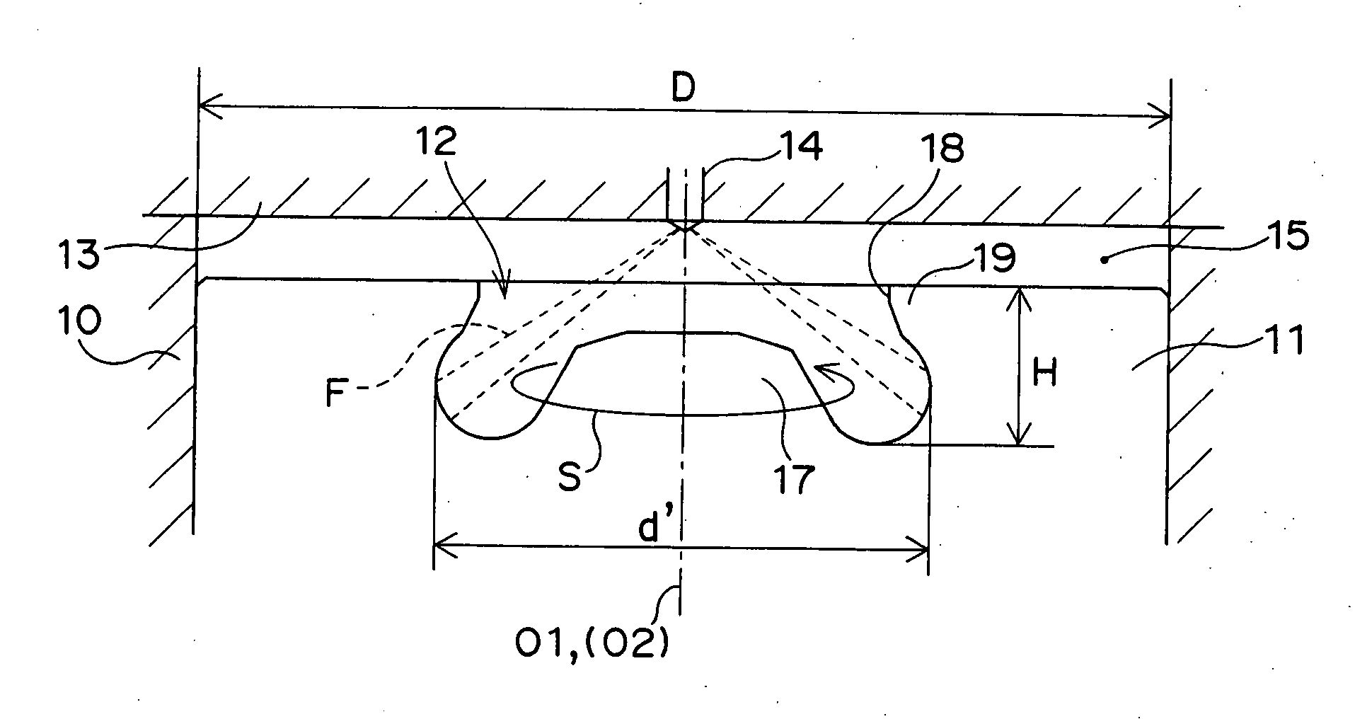
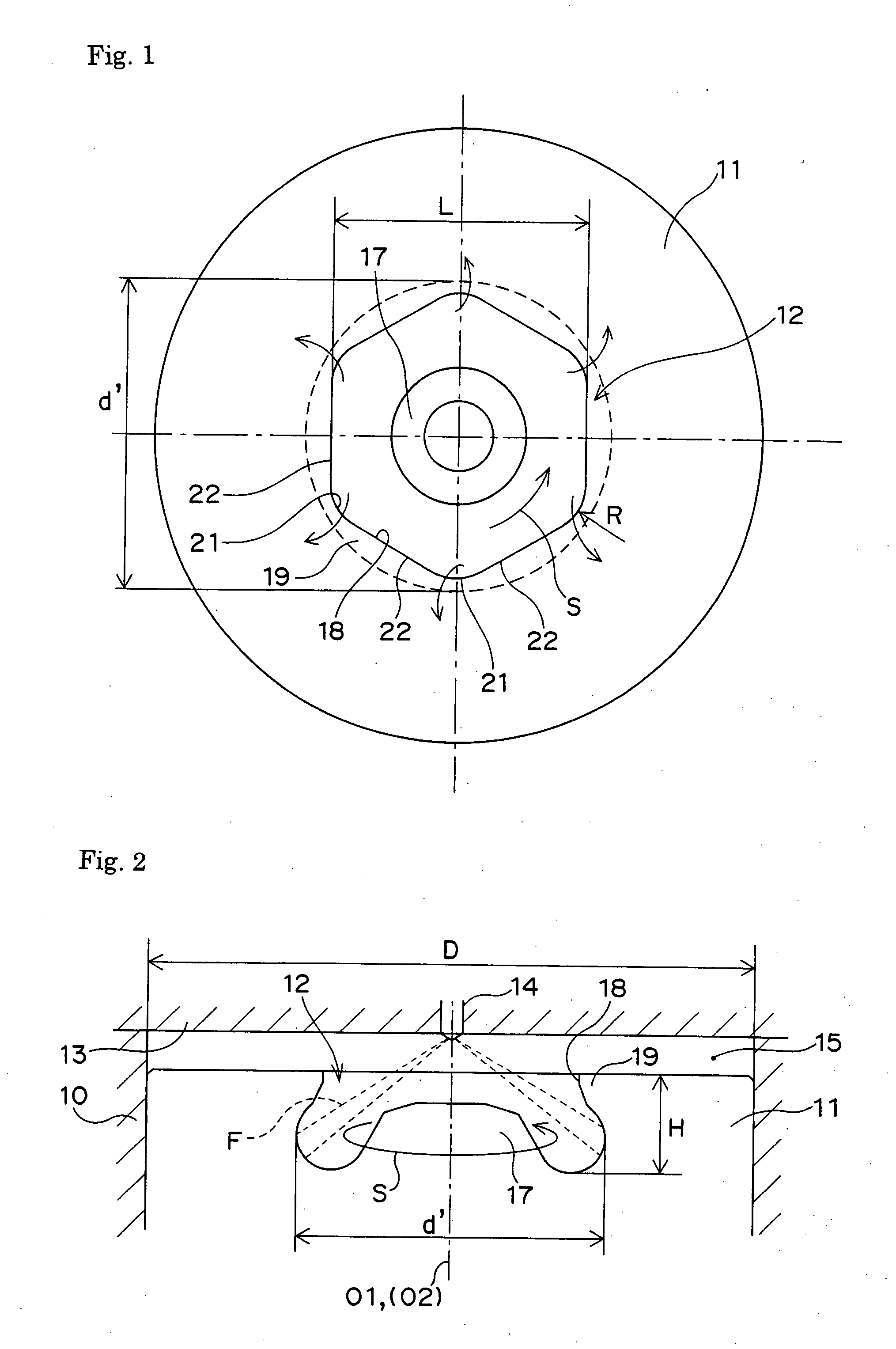
[0038]FIG. 1 is a plan view showing a top of a piston in a direct-injection diesel engine, to which the present invention is applied; and FIG. 2 is a cross-sectional view showing a combustion chamber at the top of the piston. As shown in FIGS. 1 and 2, a piston 11 is fitted into a cylinder liner 10 in a cylinder block, a recessed combustion chamber 12 (i.e., a cavity) is formed at a top of the piston 11, and an upper portion of the combustion chamber 12 is closed with a lower surface of a cylinder head 13. A fuel injection valve 14 whose center of an injection port is located on a cylinder center line (i.e., a piston center axis) O1 is fixed to the cylinder head 13. As a consequence, the fuel injection valve 14 is adapted to conically inject fuel toward the inside of the combustion chamber 12. The fuel injected into the combustion chamber 12 is mixed with intake air inside of the combustion chamber 12, and then, the resultant mixture air is burnt inside...


PUM


Abstract

The invention relates to a shape of a combustion chamber for a direct-injection diesel engine, in which a mixture in, particularly, an expansion stroke is promoted by optimally designing the shape of the combustion chamber, and further, the compatibility between PM reduction and NOx reduction can be achieved by improving a retardation limit and speeding up combustion at a high EGR. The inside of a combustion chamber 12 formed at a top of a piston is formed in such a manner that a vertically cross-sectional shape passing a center axis O2 inside of the combustion chamber is symmetric with respect to the center axis. Furthermore, an opening 18 at an upper end of the combustion chamber 12 is formed into a substantially polygonal shape in combination of round portions 21 and straight portions 22.

Description

TECHNICAL FIELD [0001] The present invention relates to a shape of a combustion chamber for a direct-injection diesel engine. BACKGROUND ART [0002] In a diesel engine of this type, a severe emission control has been imposed year to year in accordance with a recently increased attention to environmental issues. In particular, NOx and a particulate matter (hereinafter abbreviated as “PM”) among harmful substances contained in exhaust gas have been required to be reduced. [0003] However, NOx is liable to be generated in a complete combustion state: in contrast, the PM is liable to be generated in an incomplete combustion state. Therefore, NOx and the PM have the relationship of a trade-off: namely, one is decreased in exhaust amount while the other is increased in exhaust amount. As a consequence, the simultaneous reduction of the exhaust amount of both of NOx and PM is an important problem to be solved in the field of the diesel engine. [0004] Examples of means conventionally adopted ...

Claims


Application Information

Patent Timeline
Patent Type & Authority Applications(United States)
IPC IPC(8): F02F3/26F02F3/00
CPCF02B3/06F02B23/0621F02B23/0624F02B23/0651Y02T10/123F02B23/0672F02B2275/14Y02T10/125F02B23/0669Y02T10/12F02B23/00F02B23/06F02F3/26
Inventor YUZAKI, KEIICHIROFUJII, HIROYUKI
Owner YANMAR POWER TECHNOLOGY CO LTD
Why Eureka
Try Eureka