Real-Time Production-Side Monitoring and Control for Heat Assisted Fluid Recovery Applications

a technology of production-side monitoring and control, applied in survey, borehole/well accessories, construction, etc., can solve the problems of damage to the downhole, inability to recover oil conventionally, and inability to achieve the effect of reducing the risk of affecting the operation life of the downhol

Inactive Publication Date: 2007-08-30
SCHLUMBERGER TECH CORP
View PDF7 Cites 91 Cited by
  • Summary
  • Abstract
  • Description
  • Claims
  • Application Information

AI Technical Summary

Benefits of technology

[0011] It is therefore an object of the invention to provide a mechanism that protects downhole equipment from the high temperatures that result from the breakthrough of injection vapor in heat assisted production applications.
[0012] It is another object of the invention to provide a mechanism that protects surface equipment from the high temperatures that result from the breakthrough of injection vapor in heat assisted production applications.
[0014] It will be appreciated that by automatically turning off the downhole equipment while injection vapor breakthrough passes by the downhole equipment, damage to the downhole equipment can be avoided and its operational life increased. Similarly, by directing the injection vapor breakthrough along a bypass path, damage to the surface equipment can be avoided and its operational life increased.

Problems solved by technology

There are many petroleum-bearing formations from which oil cannot be recovered by conventional means because the oil is so viscous that it will not flow from the formation to a conventional oil well.
However, the downhole ESP can be damaged (or its operational lifetime adversely impacted) by the periodic direct breakthrough of injection vapor, which is referred to herein as “injection vapor breakthrough.” The injection vapor is commonly supplied to the injection well 8 at a temperature on the order of 260° C. When injection vapor breakthrough occurs, injection vapor enters the production well without experiencing significant cooling relative to its hot temperature as supplied to the injection well.
The high temperature of the injection vapor breakthrough can damage the downhole ESP when it is running and / or can adversely impact its operational life.
Similar problems can be experienced by surface equipment, such as a multiphase flow meter.
Such multiphase flow meters can be damaged, or their operational life shortened significantly, by the high temperatures that result from injection vapor breakthrough.

Method used


Image

  • Real-Time Production-Side Monitoring and Control for Heat Assisted Fluid Recovery Applications
  • Real-Time Production-Side Monitoring and Control for Heat Assisted Fluid Recovery Applications
  • Real-Time Production-Side Monitoring and Control for Heat Assisted Fluid Recovery Applications

Examples


Embodiment Construction

[0020] In the description, the terms “downstream” and “upstream”; “downhole” and “uphole”; “down” and “up”; “upward” and “downward”; and other like terms indicate relative positions in a wellbore relative to the direction of fluid flow therein. In other words, fluid flows from “upstream” locations and elements to “downstream” locations and elements. Note that when applied to apparatus and methods for use in wellbores that are deviated or horizontal, such terms may refer to a left to right relationship, right to left relationship, or other relationships as appropriate.

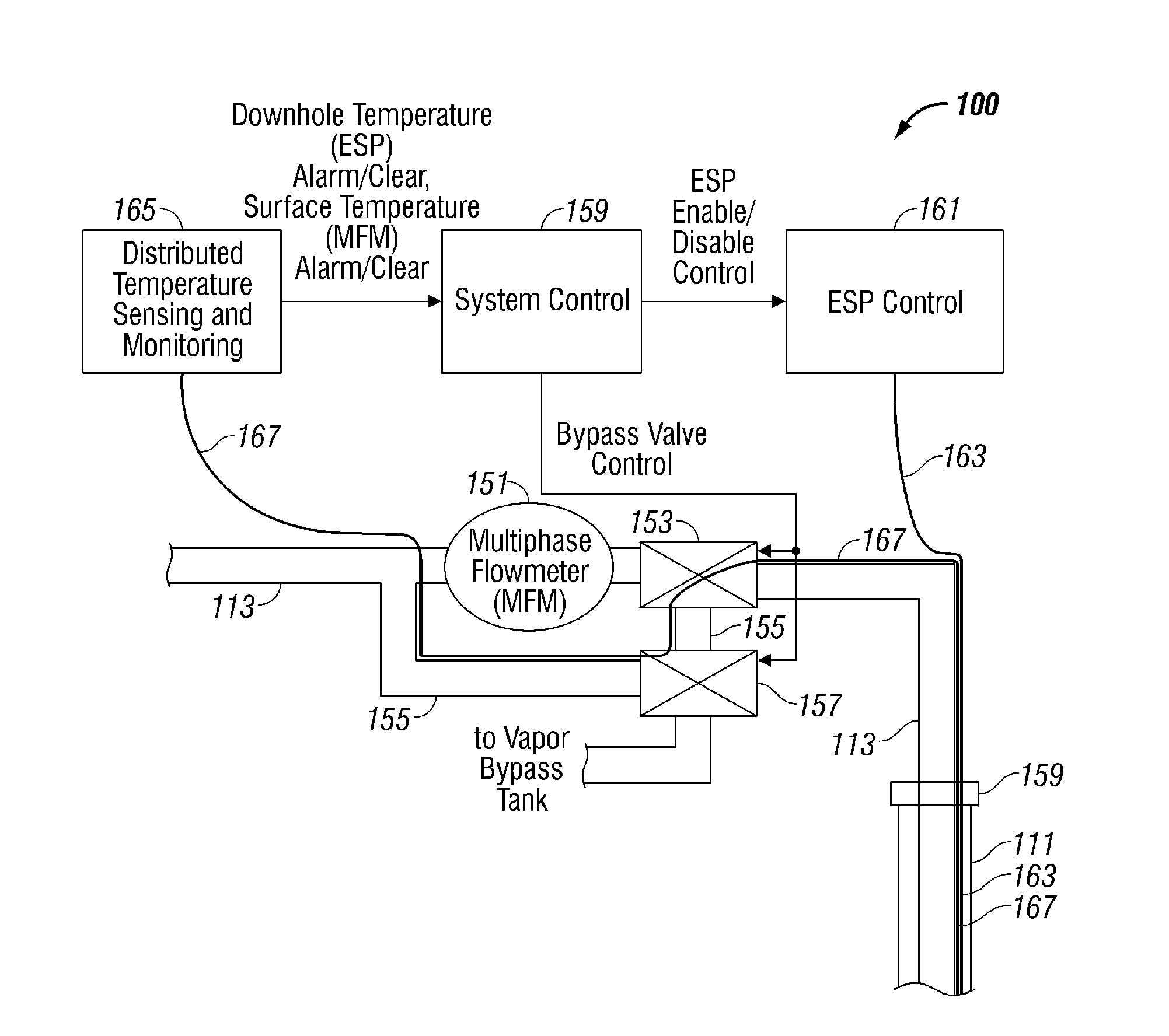
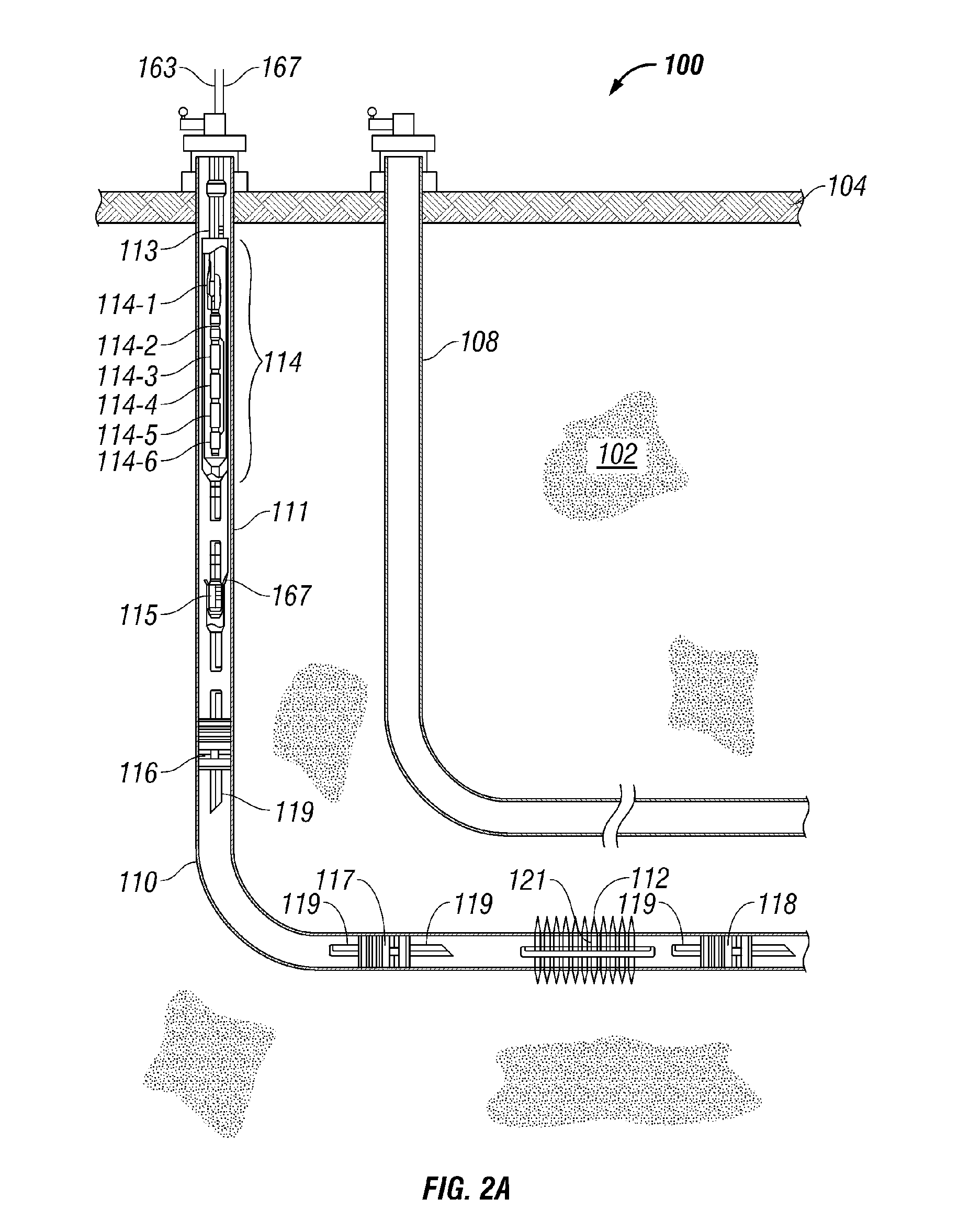
[0021] Turning now to FIGS. 2A and 2B, there is shown an improved steam-assisted gravity drainage system 100 in accordance with the present invention. The system incorporates an automatic control system that protects downhole equipment and surface equipment from the high temperatures that result from the breakthrough of injection vapor.

[0022] As is conventional, the system 100 employs a stacked pair of horizontal well...


PUM


Abstract

An automatic control system that protects downhole equipment and surface equipment from high temperatures resulting from the breakthrough of injection vapor. The system operates to derive an estimate of the temperature of production fluid at a location upstream from the downhole equipment. An alarm signal is generated in the event that this temperature exceeds a threshold temperature characteristic of injection vapor breakthrough. Electric power to the downhole equipment is automatically shut off in response to receiving the alarm signal. A bypass valve selectively directs production fluid to a bypass path. The system operates to derive an estimate of the temperature of the production fluid at a location upstream from the surface equipment. An alarm signal is generated when this temperature exceeds a threshold temperature characteristic of injection vapor breakthrough. The bypass valve is automatically controlled to direct production fluid to the bypass path in response to receiving the alarm signal.

Description

BACKGROUND OF THE INVENTION [0001] 1. Field of the Invention [0002] This invention relates broadly to apparatus and processes for recovering fluid by injection of hot vapor or other heat assisted production techniques. More particularly, this invention relates to apparatus and processes for recovering natural bitumen and other forms of heavy oil by heat assisted production techniques. [0003] 2. Description of Related Art [0004] There are many petroleum-bearing formations from which oil cannot be recovered by conventional means because the oil is so viscous that it will not flow from the formation to a conventional oil well. Examples of such formations are the bitumen deposits in Canada and in the United States and the heavy oil deposits in Canada, the United States, and Venezuela. In these deposits, the oil is so viscous, under the prevailing temperatures and pressures within the formations, that it flows very slowly (or not at all) in response to the force of gravity. Heavy oil is ...

Claims


Application Information

Patent Timeline
Patent Type & Authority Applications(United States)
IPC IPC(8): E21B43/24E21B47/07
CPCE21B43/2406E21B47/123E21B47/065E21B47/07E21B47/135
Inventor WALFORD, MERRICK
Owner SCHLUMBERGER TECH CORP
Why Eureka
Try Eureka