Three-dimensional liquid chromatography

a liquid chromatography and three-dimensional technology, applied in the direction of chemical indicators, separation processes, instruments, etc., can solve the problems of impeded component separation in the reversed-phase column, inability to successfully perform the separation of hydrophilic components such as indicated by sample groups c and d, etc., to achieve the effect of improving the separation capability

Inactive Publication Date: 2007-08-30
HITACHI HIGH-TECH CORP
View PDF7 Cites 45 Cited by
  • Summary
  • Abstract
  • Description
  • Claims
  • Application Information

AI Technical Summary

Benefits of technology

[0011] In a liquid chromatography apparatus of the present invention, a separation column of intermediate stage is additionally connected between a separation column of first stage and a separation column of second stage. Preferably, a switching unit and a liquid feed unit for mixing and feeding a plurality of solutions are added to improve a separation capability.
[0012] According to the present invention, a three-dimensional liquid chromatography apparatus capable of avoiding the “solution interference” can be realized. As a result, even a complex sample containing a hydrophilic component and a hydrophobic component in a mixed state can be separated and analyzed satisfactorily on-line.

Problems solved by technology

As seen from Table 1, in the case of employing the above-mentioned column combination, separation of hydrophilic components such as indicated by sample groups C and D cannot be successfully performed.
In that case, however, an organic solvent used for the component separation in the normal-phase column impedes the component separation in the reversed-phase column.

Method used


Image

  • Three-dimensional liquid chromatography
  • Three-dimensional liquid chromatography
  • Three-dimensional liquid chromatography

Examples


first embodiment

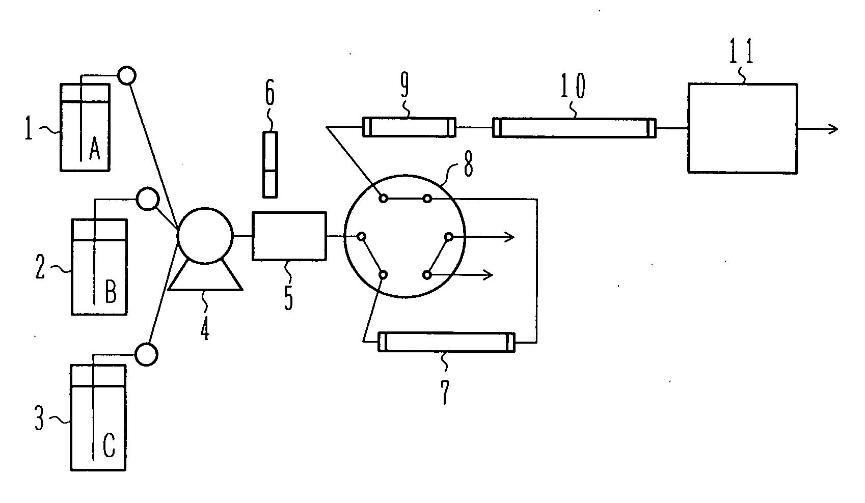
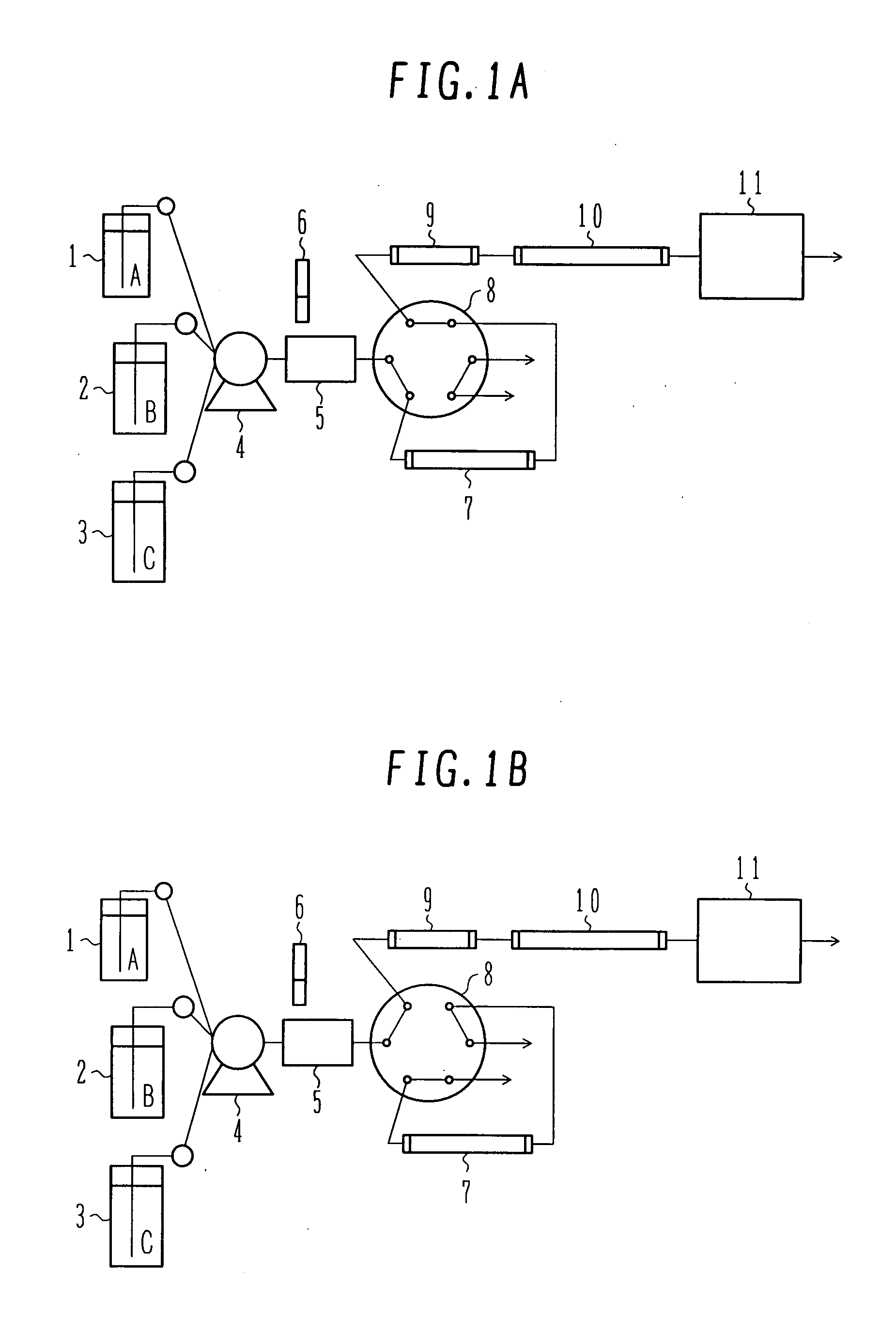
[0019]FIG. 1 represents a first embodiment of the present invention and shows a three-dimensional liquid chromatography apparatus having the simplest construction. The functions and operating principles of component units are described below.

[0020] The three-dimensional liquid chromatography apparatus of the first embodiment comprises a gradient pump 4, a sample injection unit (means), a normal-phase column 7 serving as a separation column of first stage, a reversed-phase column 10 serving as a separation column of second stage, a 6-way flow passage switching valve 8 serving as a switching unit (means), and a mass spectrometer 11 serving as a detection unit (means) for detecting separated components. In addition, an ion-exchange column 9 serving as a separation column of intermediate stage is connected between the switching unit and the separation column of second stage.

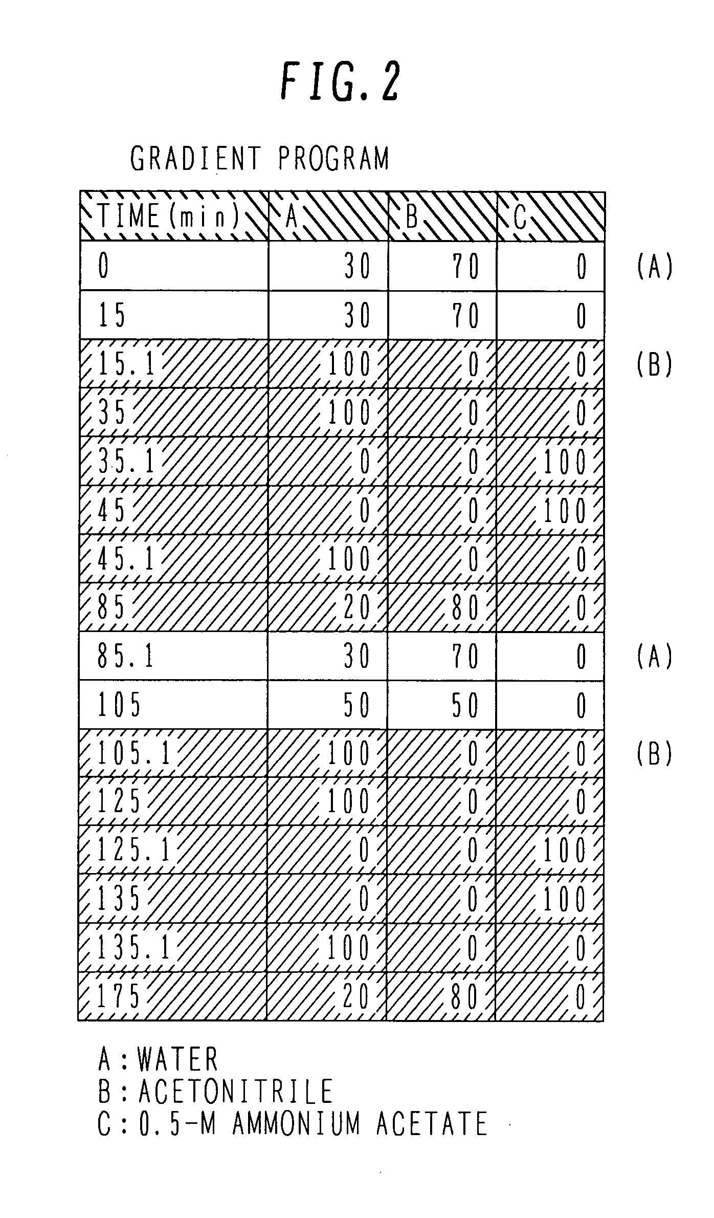
[0021] The gradient pump 4 serves as a liquid feed unit (means) for mixing and feeding a plurality of solutions....

second embodiment

[0034]FIG. 5 shows a second embodiment of the present invention. The second embodiment differs from the first embodiment in adding two 6-way flow passage switching valves and a reversed-phase trap column so that solutions can be fed at the solution composition suitable for each separation column by using three pumps. The following description is made of primarily points differing from the first embodiment.

[0035] A three-dimensional liquid chromatography apparatus of the second embodiment comprises a first gradient pump 27, a second gradient pump 28, an auto-sampler 30 serving as a sample injection unit (means), a normal-phase column 31 serving as a separation column of first stage, a cation (anion)-exchange column 32 serving as a separation column of intermediate stage, a reversed-phase column 36 serving as a separation column of second stage, a first 6-way flow passage switching valve 34, and a mass spectrometer 37. In addition, a second 6-way flow passage switching valve 35 and a...


PUM


Abstract

In a liquid chromatography apparatus, a separation column of intermediate stage is additionally connected between a separation column of first stage and a separation column of second stage. Preferably, a switching unit and a liquid feed unit for mixing and feeding a plurality of solutions are added to improve a separation capability. A three-dimensional liquid chromatography apparatus capable of avoiding the “solution interference” can be realized. Even a complex sample containing a hydrophilic component and a hydrophobic component in a mixed state can be separated and analyzed satisfactorily on-line.

Description

BACKGROUND OF THE INVENTION [0001] 1. Field of the Invention [0002] The present invention relates to a liquid chromatography apparatus. More specifically, the present invention relates to a three-dimensional liquid chromatography apparatus including, for example, a normal-phase, ion-exchange, and reversed-phase separation columns. [0003] 2. Description of the Related Art [0004] In a complex biotic sample, a hydrophilic component, a hydrophobic component, and an ionic component are mixed and the molecular weight of each component is distributed over a wide range. Accordingly, there is a limit in separating the components by one type of column. To overcome such a limit, two-dimensional liquid chromatography apparatuses each using a combination of two types of columns operating based on different separation modes are proposed (see Non-Patent Document 1: A. J. Link et al, Nat. Biotechnol. 17, 676 (1999), Non-Patent Document 2: Y. Shen et al, Anal. Chem. 77, 3090 (2005), Non-Patent Docum...

Claims


Application Information

Patent Timeline
Patent Type & Authority Applications(United States)
IPC IPC(8): B01D15/08
CPCG01N30/463G01N30/96G01N30/7233G01N30/461B01D15/322B01D15/362B01D15/325B01D15/363
Inventor ITO, MASAHITOMIURA, JUNKICHIDEGUCHI, KISABURO
Owner HITACHI HIGH-TECH CORP
Why Eureka
Try Eureka